
Beverage dispensing machine

a beverage dispenser and machine body technology, applied in beverage vessels, domestic applications, tea, etc., can solve the problems of resistor sheath corrosion by water, difficulty in controlling the temperature of the resistor within the heater, and tendency to be very rapidly coated, so as to improve the heat transmission

Active Publication Date: 2013-01-31
I R C A S P A IND RESISTENZE CORAZZATE E AFFINI
View PDF5 Cites 4 Cited by
  • Summary
  • Abstract
  • Description
  • Claims
  • Application Information

AI Technical Summary

Benefits of technology

The present invention provides a hot beverage dispensing machine with a liquid heater that improves heat transmission to its control / safe devices. The heater is designed in a compact manner to accommodate the control / safe devices. This machine allows for indirect heating of a liquid through its plates and fluid means, which reduces the accumulation of saline and metal residues in the water circuit, without altering it or compromising the performance of the heater.

Problems solved by technology

This, however, tends to be very rapidly coated by the solid residues dissolved in the liquid to be heated, particularly when the water is hard.
This type of heater is not of the preferred type because the heated water is intended for human consumption.
The position of the heating circuit in the heating liquid causes the problem of accumulation of solid residues within the heated circuit and the formation of lime scale, which encrusts the resistor and parts of the heater.
Other disadvantages which appear in these heaters are the possibility of corrosion of the resistor sheath by the water, which may come into contact with electric parts, and the difficulty of controlling the temperature of the resistor within the heater.
A further disadvantage is the need for the fluid to be present in the heater before starting to heat, or at least for the fluid to cover the heating element, and that the fluid level is maintained during operation.
However, specific supporting means are disadvantageously needed to accommodate and support the control / safety devices, e.g. comprising a thermostat.
Said supporting means (despite being made of aluminium) thus form in turn a heating resistor, worsening thermal transmission towards the devices themselves.
Alternatively, these control / safety devices are directly fixed to a steel wall of the container cap, worsening in all cases heat transmission to the devices themselves.

Method used


Image

  • Beverage dispensing machine
  • Beverage dispensing machine
  • Beverage dispensing machine

Examples


Embodiment Construction

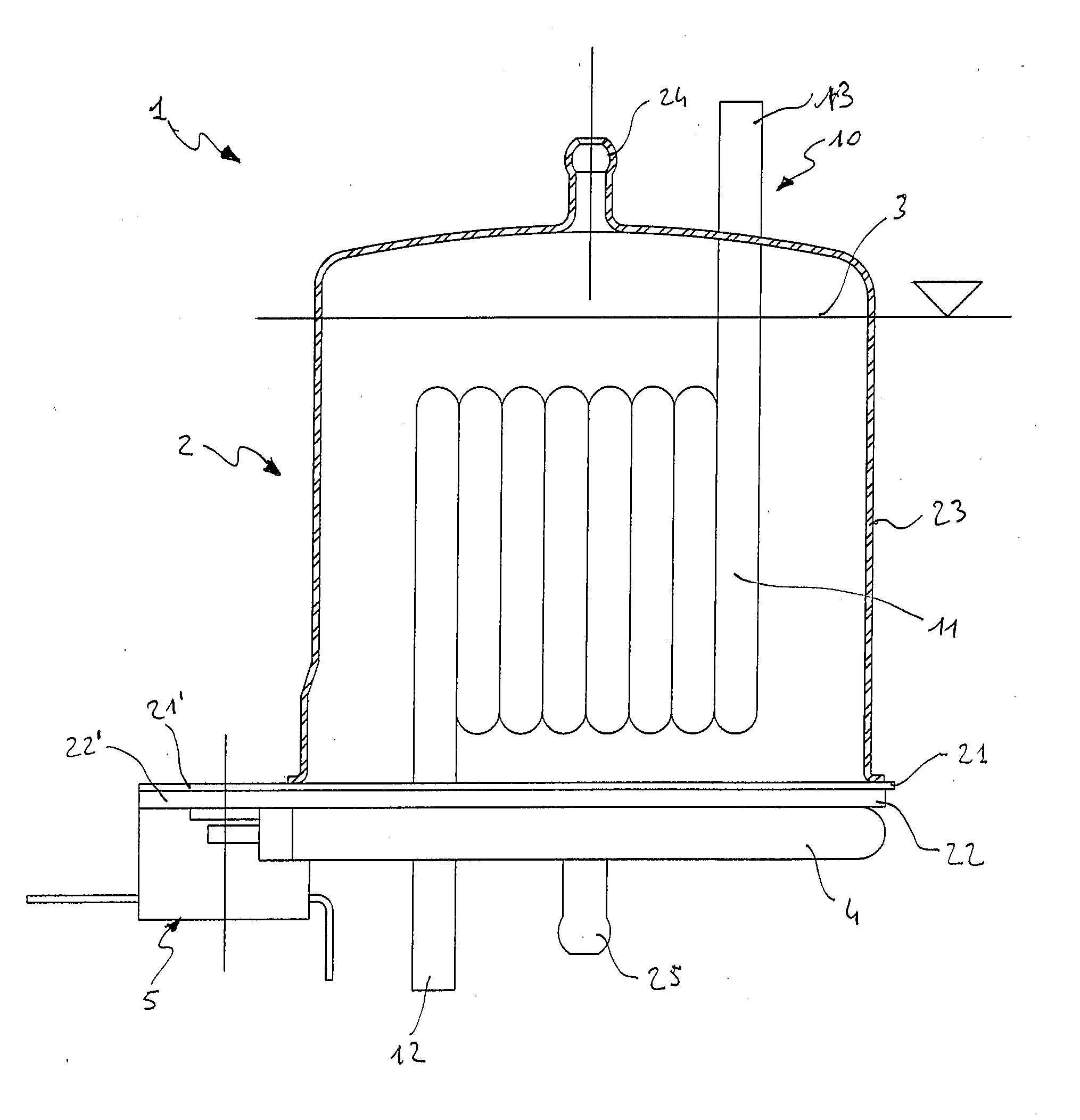
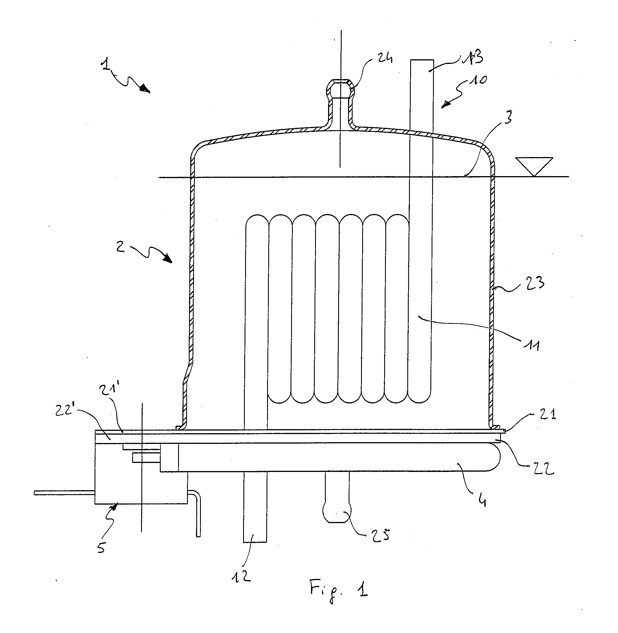
[0041]The heater of a hot beverage dispensing machine, object of the present invention, according to FIGS. 1 and 7, comprises a container 2 filled with a liquid 3, which in the specific example is water. An electric heating resistor 4, best seen in FIG. 2, is arranged outside on the base of container 2, which resistor heats the liquid 3 within the container itself.

[0042]In a first variant, a heating water circuit segment or pipe 10, possibly comprising a spiral-shaped segment 11, i.e. a segment wound as a spiral, is immersed in liquid 3.

[0043]The ends 12 and 13 of the heating water circuit segment 10 are adapted to be connected to an external circuit, through which a further liquid to be heated circulates. In particular, the end 12 for introducing the liquid to be heated preferably crosses the base of container 2, i.e. it is on the same side as the electric resistor 4 when suitably orientating the heater for working. Extremities 12 and 13 preferably cross the container 2 from opposi...


PUM


Abstract

A machine for dispensing hot beverages, e.g. coffee, comprising a liquid heater, in particular for heating water intended for human consumption, provided with a container, adapted to be at least partially filled with a first liquid to be heated, and a heating electric resistor arranged outside the container, in contact with the bottom of said container, so as to indirectly heat said first liquid through said bottom.

Description

FIELD OF THE INVENTION[0001]The present invention relates to a machine for dispensing hot beverages, such as coffee, comprising a liquid heater, in particular for heating water intended for human consumption.STATE OF THE ART[0002]Hot beverage dispensing machines comprise liquid, particularly water, heaters. In particular, electric heaters are the most commonly used when hot water is required very quickly.[0003]A first type of heaters comprises a container, through which the liquid to be heated flows, in which an electric serpentine is submerged.[0004]This, however, tends to be very rapidly coated by the solid residues dissolved in the liquid to be heated, particularly when the water is hard.[0005]This type of heater is not of the preferred type because the heated water is intended for human consumption.[0006]For this purpose, the known art suggests heaters which comprise a water heating circuit about which an electric resistor is externally wound. Therefore, the passage of liquid th...

Claims


Application Information

Patent Timeline
IPC IPC(8): A23F5/00
CPCA47J31/542A47J31/54
Inventor VIRZI, ANDREACAPRARO, DUILIOCEOTTA, CHRISTIANFOLTRAN, VANIA
Owner I R C A S P A IND RESISTENZE CORAZZATE E AFFINI
Learn More