Circuit breaker lockout system with tie-receiving channels

a circuit breaker and lockout technology, applied in the direction of electrical equipment, switches with electrothermal and electromagnetic release, protective switch operating/release mechanisms, etc., can solve the problems of increasing the risk of fod, and reducing the useable workspace of technicians

Active Publication Date: 2018-05-08
THE BOEING CO
View PDF5 Cites 0 Cited by
  • Summary
  • Abstract
  • Description
  • Claims
  • Application Information

AI Technical Summary

Benefits of technology

[0010]A lockout system is provided for preventing a manually operated push-pull circuit breaker from being inadvertently depressed once it has been disengaged while personnel are working on or near de-energized equipment or circuits. In one example, the lockout system may include an attachment member having a generally C-shaped collar defining a cylindrical recess therein. The attachment member is configured to be resiliently expanded such that the C-shaped collar is positioned over and receives a cylindrical portion of the circuit breaker knob when the circuit breaker has been manually extended (e.g., by pulling) or automatically extended (i.e., by popping out).

Problems solved by technology

First, existing lockout devices are bulky and often protrude out from the circuit breaker panel. In some instances, the lock-out devices may protrude from the circuit panel more than an inch or so. This protrusion reduces the useable workspace of a technician because the passageways in electrical bays (“E-bay”) of aircraft structures may be very tight and, as such, technicians may frequently snag or bump into the lockout device while passing through the E-bay. Because circuit breaker knobs are not intended to be loaded, only to be pushed in or pulled out, the circuit breaker knobs upon which the lockout devices are applied may be sheared or snapped-off when the lockout devices are inadvertently engaged by a technician passing through the E-bay.
FOD often migrate around aircraft structures and the use of existing multi-part lock-out devices increases FOD risk.

Method used


Image

  • Circuit breaker lockout system with tie-receiving channels
  • Circuit breaker lockout system with tie-receiving channels
  • Circuit breaker lockout system with tie-receiving channels

Examples


Embodiment Construction

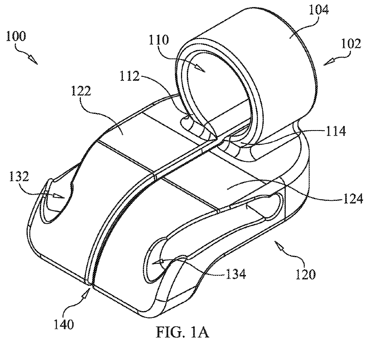
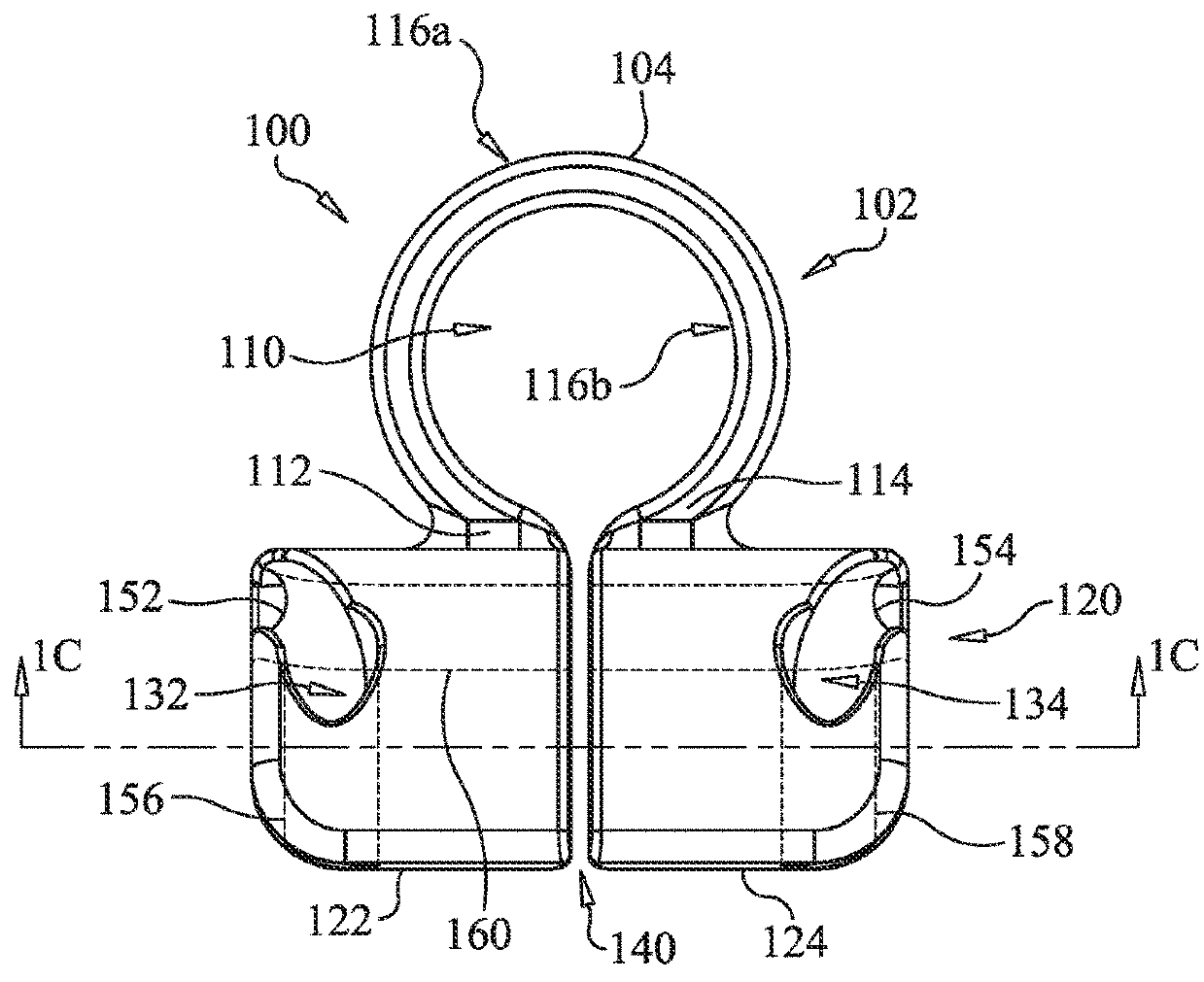
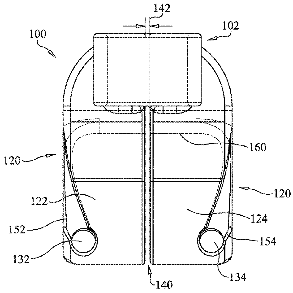
[0032]A lockout system of preventing a manually operated push-pull circuit breaker from being inadvertently depressed once it has been disengaged while personnel are working on or near de-energized equipment or circuits is provided. FIG. 1A shows a perspective view of an example of a lockout device 100 comprising an attachment member together with an integrated (i.e., one piece) retainer member of a lockout system for preventing an extended push-pull circuit breaker from being depressed, in accordance the present disclosure. In FIG. 1A, attachment member 102 is shown having a generally C-shaped collar 104 defining a cylindrical recess 110 therein and having a first free end 112 and a second free end 114.

[0033]Depending from the attachment member 102 is retainer member 120, which is attached to the attachment member 102 at its first free end 112 and its second free end 114. The retainer member 120 includes a first channel member 122 and a second channel member 124 wherein each channe...


PUM


Abstract

A lockout system for preventing a push-pull circuit breaker from being depressed while personnel work on de-energized electrical equipment. The lockout system includes an attachment member having a generally C-shaped collar defining a cylindrical recess integrated with a retainer member. The C-shaped collar is configured to resiliently expand in order to be positioned over and receive a cylindrical portion of an extended circuit breaker knob such that engagement of the circuit breaker is prevented. The retainer member includes a first channel member and a second channel member, each with a channel connected by a crossover channel that forms a continuous channel configured to receive a wire cable. Once inserted, the wire cable is firmly held in place by a locking chamber attached at each end of the wire cable, and thereafter, the lockout device can only be removed by a cutting the wire cable with a wire cutting tool.

Description

BACKGROUND1. Technical Field[0001]The present disclosure generally relates to affixing appropriate lockout devices to energy isolating devices and, more particularly, to a system and method for preventing the inadvertent engagement of a manually operated push-pull electrical circuit breaker on a circuit breaker panel.2. Background of the Invention[0002]Under regulations of the U.S. Occupational Safety and Health Administration (“OSHA”), e.g., Control of Hazardous Energy (Lock-Out / Tag-Out) (“LOTO”) standards, Title 29, Code of Federal Regulations (CFR) Parts 1910.147 and 1910.333, employers are required to establish programs and establish procedures for affixing appropriate lockout and tagout devices to energy isolating devices to prevent unexpected energization or start up or release of stored energy whenever work is performed near or on equipment or circuits that are or may be energized, in order to prevent electric shock or other injuries to employees.[0003]Energy isolating device...

Claims


Application Information

Patent Timeline
Patent Type & Authority Patents(United States)
IPC IPC(8): H01H9/28H01H9/20H01H71/10
CPCH01H9/20H01H71/1054H01H9/287H01H9/286H01H71/58H01H73/56
Inventor DIXON, ROBERT DEANSWINEFORD, THOMAS R.
Owner THE BOEING CO
Why Eureka
Try Eureka