Connector

a technology of connecting parts and contacts, applied in the direction of coupling contact parts, coupling device connections, coupling contact parts, etc., can solve the problems of deteriorating connection reliability between the first terminal and the short-circuiting terminal, damage or deformation of the contact portion, etc., to achieve the effect of stabilizing the displacement of the contact pi

Active Publication Date: 2018-05-15
YAZAKI CORP
View PDF18 Cites 0 Cited by
  • Summary
  • Abstract
  • Description
  • Claims
  • Application Information

AI Technical Summary

Benefits of technology

[0019]Since when the first housing and the second housing are fit together, the release portion has a displacement portion that slides on the sliding protrusion to displace the contact piece in a direction away from the sliding slope, the sliding movement between the sliding protrusion and the sliding slope can be maintained by the restoring force of the contact piece. Thus, the release portion can stabilize the displacement of the contact piece.
[0020]A connector according to the aspect of the present invention provides a connector capable of ensuring connection reliability between a first terminal and a short-circuiting terminal.

Problems solved by technology

However, when the contact portion of the contact piece slides on the release portion as in the connector of JP 06-181083 A, damage or deformation may occur on the contact portion.
Thus, the connection reliability between the first terminal and the short-circuiting terminal may deteriorate.

Method used


Image

  • Connector
  • Connector
  • Connector

Examples


Embodiment Construction

[0031]A connector according to an embodiment of the present invention will be described with reference to FIGS. 1 to 10.

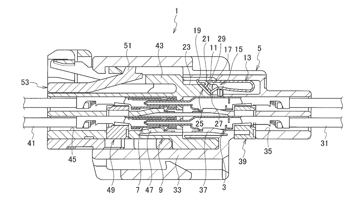
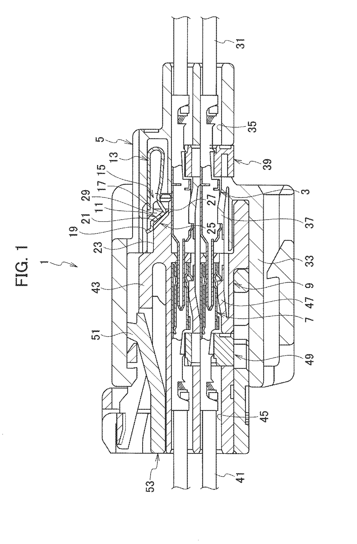
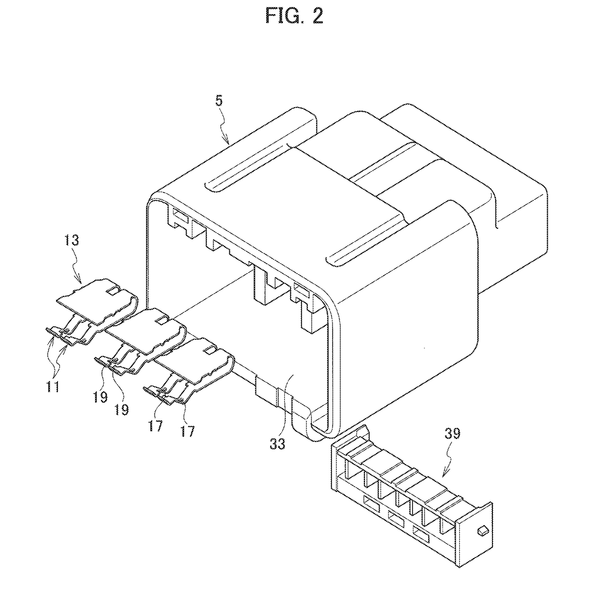
[0032]The connector 1 according to the present embodiment includes a first housing 5 housing a plurality of first terminals 3, a second housing 9 housing a plurality of second terminals 7 connectable to the respective first terminals 3, the second housing 9 being fittable to the first housing 5, a short-circuiting terminal 13 housed in the first housing 5, the short-circuiting terminal 13 having contact pieces 11, 11 contacting the respective first terminals 3, 3 which are adjacent to each other, and a release portion 15 provided on the second housing 9, the release portion 15 displacing the contact pieces 11 to release contact between the first terminals 3 and the contact pieces 11.

[0033]The contact piece includes a contact portion provided so as to be in contact with the first terminal, and a sliding protrusion protruding from the contact portion in a direction i...


PUM


Abstract

A connector includes a first housing, a second housing, a short-circuiting terminal, and a release portion configured to release contact between the first terminals and the contact pieces. The contact piece includes a contact portion provided to be in contact with the first terminal, and a sliding protrusion protruding from the contact portion in a direction intersecting a fitting direction of the housings. The release portion includes a sliding slope sliding on the sliding protrusion to displace the contact piece, a support portion continuously provided with the sliding slope, the support portion coming into contact with the sliding protrusion and holding the contact piece is displaced in a state, and a contact housing portion arranged from the sliding slope and the support portion in a direction crossing a fitting direction of the first housing and the second housing, the contact housing portion housing the contact portion the fitted state.

Description

CROSS REFERENCE TO RELATED APPLICATIONS[0001]This application claims the priority of Japanese Patent Application No. 2016-149200, filed on Jul. 29, 2016, the entire content of which are incorporated herein by reference.BACKGROUNDTechnical Field[0002]The present invention relates to a connector. More specifically, the present invention relates to a connector having a short-circuiting terminal for connecting a plurality of terminals housed in a housing.Related Art[0003]Conventional connectors include a first housing housing female terminals as a plurality of first terminals, a second housing housing male terminals as a plurality of second terminals connectable to the respective female terminals, wherein the second housing is fittable to the first housing, a short-circuiting terminal housed in the first housing, wherein the short-circuiting terminal has contact pieces contacting the respective female terminals which are adjacent to each other, and an insulating member as a release port...

Claims


Application Information

Patent Timeline
Patent Type & Authority Patents(United States)
IPC IPC(8): H01R13/70H01R13/703
CPCH01R13/7031H01R13/02H01R13/502H01R24/00H01R31/08H01R13/7032
Inventor SEKINO, TETSUYASAKAMOTO, NOBUYUKI
Owner YAZAKI CORP
Why Eureka
Try Eureka