Expansion joint seal with surface load transfer, intumescent, and internal sensor

a technology of expansion joints and load transfer, applied in the direction of bridges, roads, roads, etc., can solve the problems of inflexible seals, fragile or experience adhesive or cohesive failures, and systems lack the resiliency and seismic movement required in expansion joints

Active Publication Date: 2018-05-29
SCHUL INT COMPANY
View PDF149 Cites 55 Cited by
  • Summary
  • Abstract
  • Description
  • Claims
  • Application Information

AI Technical Summary

Problems solved by technology

Moreover, these joints are subject to damage over time.
Most damage is from vandalism, wear, environmental factors and when the joint movement is greater, the seal may become inflexible, fragile or experience adhesive or cohesive failure.
These systems lack the resiliency and seismic movement required in expansion joints.
These systems have been further limited in functioning as a fire-resistant barrier, which is often a desired function.
Other systems have incorporated cover plates that span the joint itself, often anchored to the concrete or attached to the expansion joint material and which are expensive to supply and install.
Additionally, cover plates that are higher than the deck or substrate level can present a hazard, such as tripping, an unnecessary impediment, such as to wheelchairs.
Further, these systems require undesirable mechanical attachment, which requires drilling into the deck or joint substrate.
Cover plate systems that are not mechanically attached rely on support or attachment to the expansion joint, thereby subject the expansion joint system to continuous compression, expansion and tension on the bond line when force is applied to the cover plate, which shortens the life of the joint system.

Method used


Image

  • Expansion joint seal with surface load transfer, intumescent, and internal sensor
  • Expansion joint seal with surface load transfer, intumescent, and internal sensor
  • Expansion joint seal with surface load transfer, intumescent, and internal sensor

Examples


Embodiment Construction

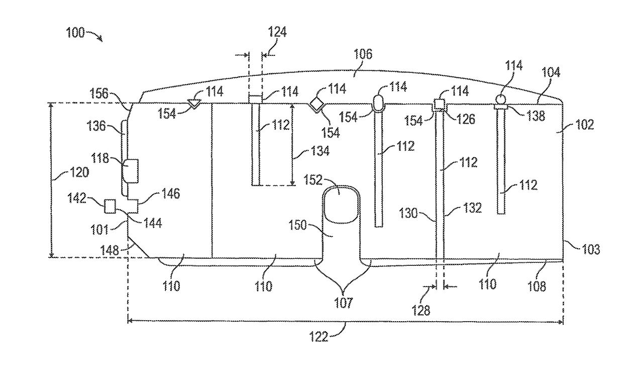
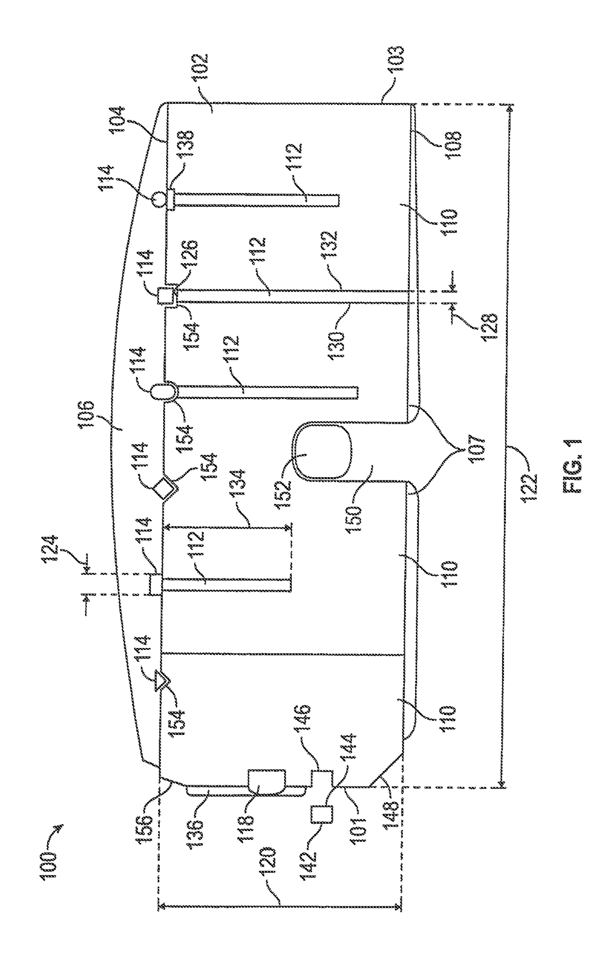
[0016]Referring to FIG. 1, an end view of one embodiment of the expansion joint system 100 of the present disclosure is provided. The system 100 includes an elongated core 102 and at least one longitudinal load-transfer member 114 which are bonded together. The system 100 provides an expansion joint system which can be used in standard applications and in exposed, high traffic areas, which is preferably water resistant.

[0017]The elongated core 102 is composed of resiliently compressible foam, which may be closed cell or open cell foam, or a combination thereof. The extent of compressibility may be selected based on the need. A higher compression is known to result in higher water resistance, but may create difficulties in installation, and ultimately becomes so compressed as to lack flexibility or further compressibility, such as at a ratio of 5:1. The elongated core 102 may be compressible by 25%, or may compress by 100% or as high as 400% so that the elongated core 102 is one quar...


PUM

PropertyMeasurementUnit
compression ratiosaaaaaaaaaa
widthaaaaaaaaaa
widthaaaaaaaaaa

Abstract

An expansion joint design for supporting transfer loads. The system includes an elongated core and at least one longitudinal load-transfer member which are bonded together.

Description

CROSS-REFERENCE TO RELATED APPLICATIONS[0001]This application is a continuation-in-part of U.S. patent application Ser. No. 15 / 648,908 for “Expansion Joint for Longitudinal Load Transfer,” filed Jul. 13, 2017, which is incorporated herein by reference, which is a continuation of U.S. patent application Ser. No. 15 / 611,160, now U.S. Pat. No. 9,739,049, for “Expansion Joint for Longitudinal Load Transfer,” filed Jun. 1, 2017, which is incorporated herein by reference, and is a continuation of U.S. patent application Ser. No. 15 / 046,924, now U.S. Pat. No. 9,745,738 for “Expansion Joint for Longitudinal Load Transfer,” filed Feb. 18, 2016, which is incorporated herein by reference, and claims priority to U.S. Provisional Patent Application No. 62 / 272,837, filed Dec. 30, 2015 for “Sealing expansion joint for longitudinal load transfer and method of manufacture,” which is incorporated herein by reference.STATEMENT REGARDING FEDERALLY SPONSORED RESEARCH OR DEVELOPMENT[0002]Not Applicable.B...

Claims


Application Information

Patent Timeline
Patent Type & Authority Patents(United States)
IPC IPC(8): E04B1/68E01D19/06E01C23/02E04F15/02
CPCE04B1/6801E01C23/026E04F15/02016E04B1/6812E01D19/06E04B1/6807E04B1/6815E01C11/12
Inventor ROBINSON, STEVEN R.
Owner SCHUL INT COMPANY
Why Eureka
Try Eureka