
Splinted compression bandage

Active Publication Date: 2018-06-05
LYNCH ALLIE
View PDF24 Cites 3 Cited by
  • Summary
  • Abstract
  • Description
  • Claims
  • Application Information

AI Technical Summary

Benefits of technology

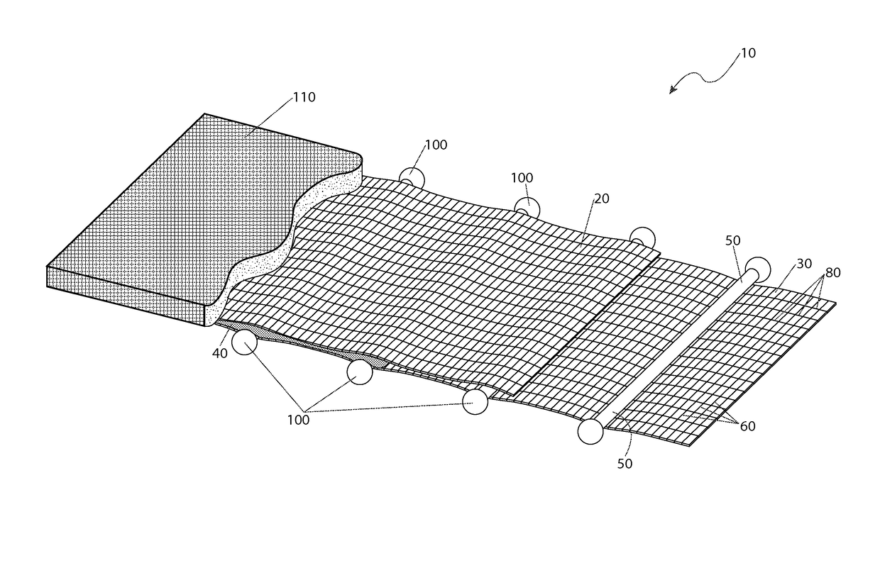
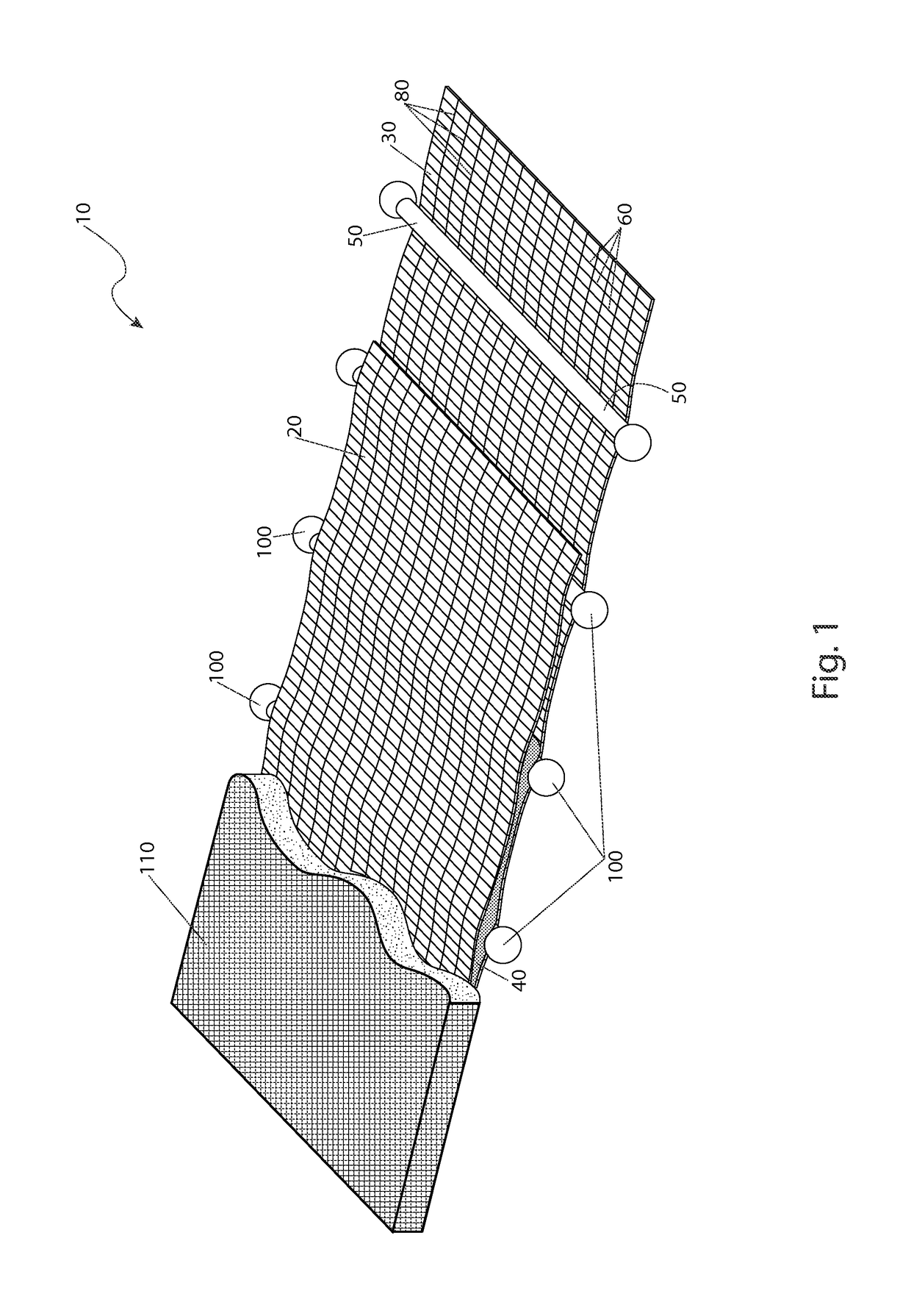
The present invention provides a medical device with moldable wires that have a torus shape at their distal ends. This helps to position the wires within the elastic layers before bonding them with adhesive. It also prevents accidental puncture of the elastic layers or the patient.

Problems solved by technology

Additionally, the immobilizing device frequently requires cutting or customization to be applicable to an individual patient, which might consume valuable time in exigent circumstances.

Method used


Image

  • Splinted compression bandage
  • Splinted compression bandage
  • Splinted compression bandage

Examples


Embodiment Construction

[0030]The best mode for carrying out the invention is presented in terms of its preferred embodiment, herein depicted within FIGS. 1 through 4, and in terms of an alternate embodiment, herein depicted in FIG. 5. However, the invention is not limited to the described embodiment and a person skilled in the art will appreciate that many other embodiments of the invention are possible without deviating from the basic concept of the invention, and that any such work around will also fall under scope of this invention. It is envisioned that other styles and configurations of the present invention can be easily incorporated into the teachings of the present invention, and only one particular configuration shall be shown and described for purposes of clarity and disclosure and not by way of limitation of scope.

[0031]The terms “a” and “an” herein do not denote a limitation of quantity, but rather denote the presence of at least one (1) of the referenced items.

[0032]The present invention desc...


PUM


Abstract

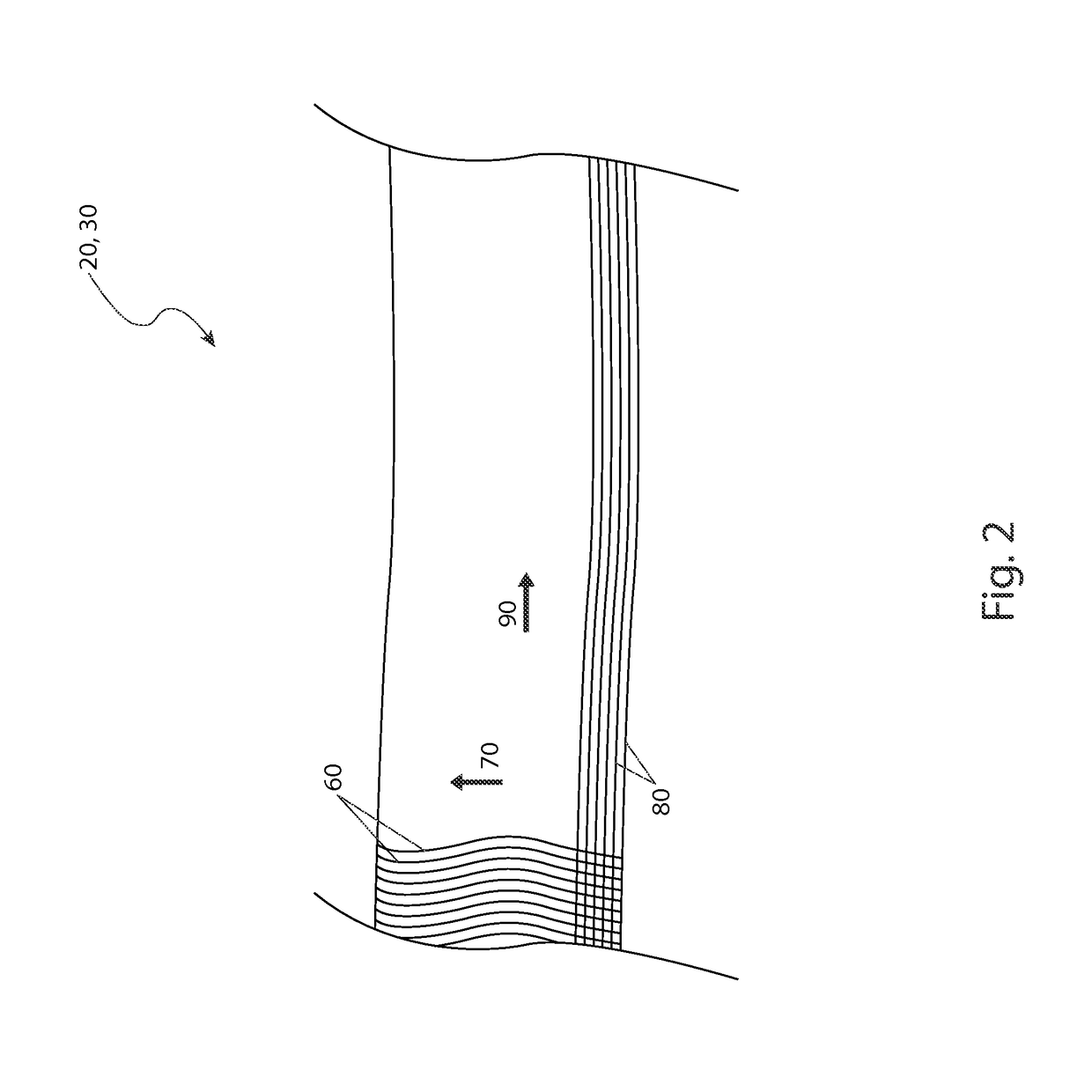
A compression-type bandaging incorporates parallel wire members operatively spaced within a pair of elastic layers such that the wire members can be shaped to conform to the limb or area that is under compression and further provide a semi-rigid splint function. Each elastic layer includes a lattice structure of threads.

Description

RELATED APPLICATIONS[0001]The present invention is a continuation-in-part of, was first described in, and claims the benefit of U.S. Provisional Application No. 61 / 914,121, filed Dec. 10, 2013, the entire disclosures of which are incorporated herein by reference.FIELD OF THE INVENTION[0002]The present invention relates generally to a compression bandage having flexible members incorporated throughout that enable the bandage to dually serve as a compression bandage and a splint.BACKGROUND OF THE INVENTION[0003]During emergency medical treatment, it is a common occurrence to apply a splint. Such splints are often used to immobilize an extremity in response to an injury, or prevent even further injury. They are frequently used in response to broken bones, sprains, and the like. In some cases, they may even be applied around torsos when dealing with spinal cord injuries. Such splints typically comprise a compression bandage and an immobilization device. The elastic nature of bandage ens...

Claims


Application Information

Patent Timeline
IPC IPC(8): A61F13/00A61F5/058A61H1/00
CPCA61H1/008A61F5/058A61F13/00029A61F13/00021A61F2013/00234A61F13/08A61F13/085A61H11/00A61H2011/005A61H2201/0157A61H2201/163A61H2201/1638A61H2201/1642A61H2201/1645A61H2201/165A61H2201/1626A61F5/05825A61F13/01021A61F13/01029
Inventor LYNCH, ALLIE
Owner LYNCH ALLIE
Learn More