Smart entry system

a technology of intelligent entry and entry system, applied in the field of smart entry system, can solve the problems of user inability to intentionally change and adjust the response distance, and cannot use the system under an operating condition, and achieve the effects of reducing the reach distance of the call signal transmitted from the transmission unit, increasing and reducing the output strength of the call signal

Inactive Publication Date: 2018-06-12
DENSO CORP
View PDF15 Cites 1 Cited by
  • Summary
  • Abstract
  • Description
  • Claims
  • Application Information

AI Technical Summary

Benefits of technology

[0009]According to this configuration, the output strength setting unit can change the output strength of the call signal. As the output strength of the call signal is increased, the call signal can be transmitted farther from the transmission unit, so that the mobile key can respond to the call signal even at a position more distant from the transmission unit. Then, the control unit performs authentication of the response signal of the mobile key, and releases the lock. That is, it is possible to release the lock even if the mobile key is at the more distant position.
[0010]In contrast, as the output strength of the call signal is decreased, the reaching distance of the call signal transmitted from the transmission unit is shortened; accordingly, the mobile key responds to the call signal at a position nearer to the transmission unit. Then, the control unit performs authentication of the response signal of the mobile key, and releases the lock. That is, it is possible to release the lock if the mobile key is at the nearer position.
[0011]Thus, in the system in which the call signal is transmitted by the polling system, it is possible to change the setting of the distance between the transmission unit and the mobile key that can respond to the call signal.

Problems solved by technology

However, the smart entry system in Patent Literature 1 does not describe the adjustment of the response distance (predetermined distance to the vehicle) of the smart key based on the call signal by the polling system.
Therefore, the user cannot intentionally change and adjust the response distance, and therefore cannot use the system under an operating condition according to the user's preference or usability.

Method used


Image

  • Smart entry system
  • Smart entry system
  • Smart entry system

Examples


first embodiment

[0017](First Embodiment)

[0018]A smart entry system 100 according to a first embodiment will be described with reference to FIGS. 1 and 2. The smart entry system 100 according to the first embodiment is a system that enables the releasing of a lock of (the unlocking of) a vehicle door (opening / closing body) without directly inserting a key into the key cylinder of the vehicle door. Further, in the smart entry system 100, when a user gets out of the vehicle and touches a predetermined part (e.g., door knob) of the closed vehicle door, a trigger signal is generated so that the vehicle door is locked.

[0019]Further, the vehicle to which the smart entry system 100 is employed can have a welcome function for turning on, e.g., a light provided on a door mirror, a headlight, an interior light, or the like when the vehicle door is unlocked.

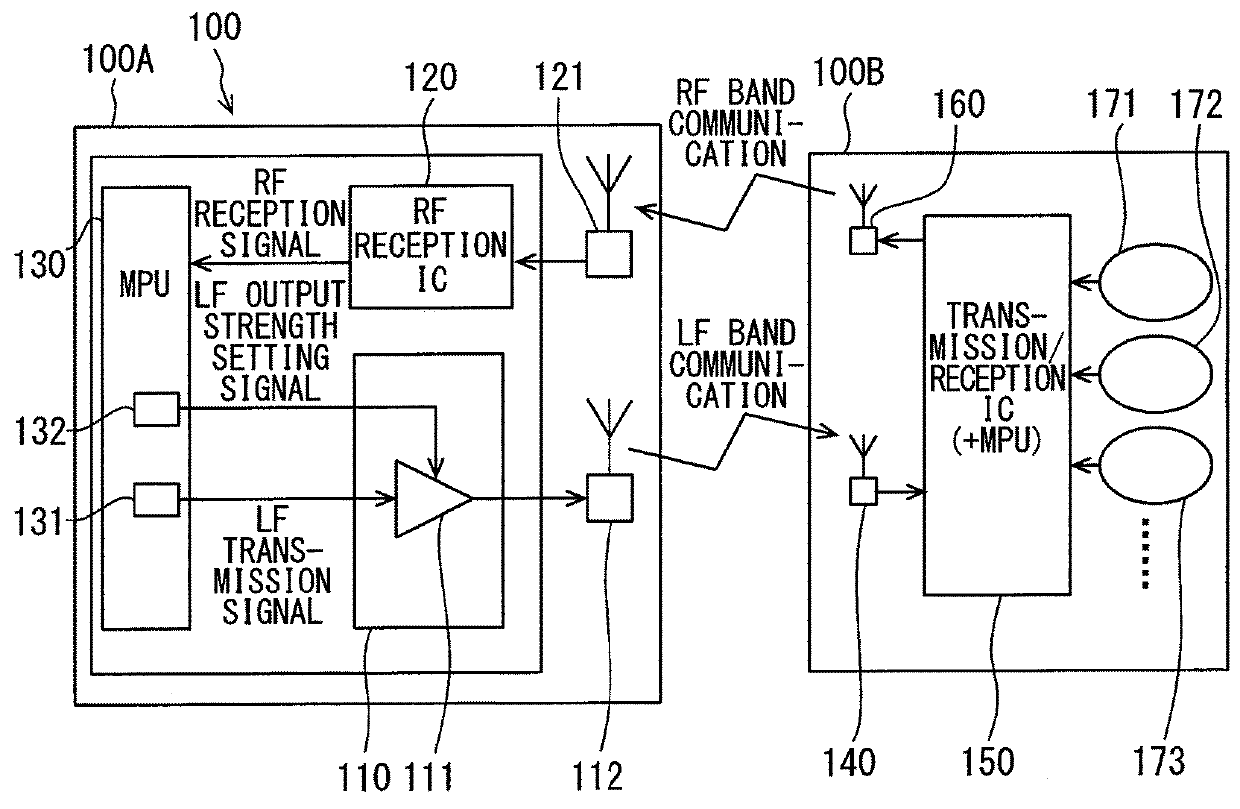
[0020]The smart entry system 100 includes a vehicle-side main body unit 100A and a mobile device 1008, as shown in FIG. 1.

[0021]The vehicle-side main body ...

second embodiment

[0061](Second Embodiment)

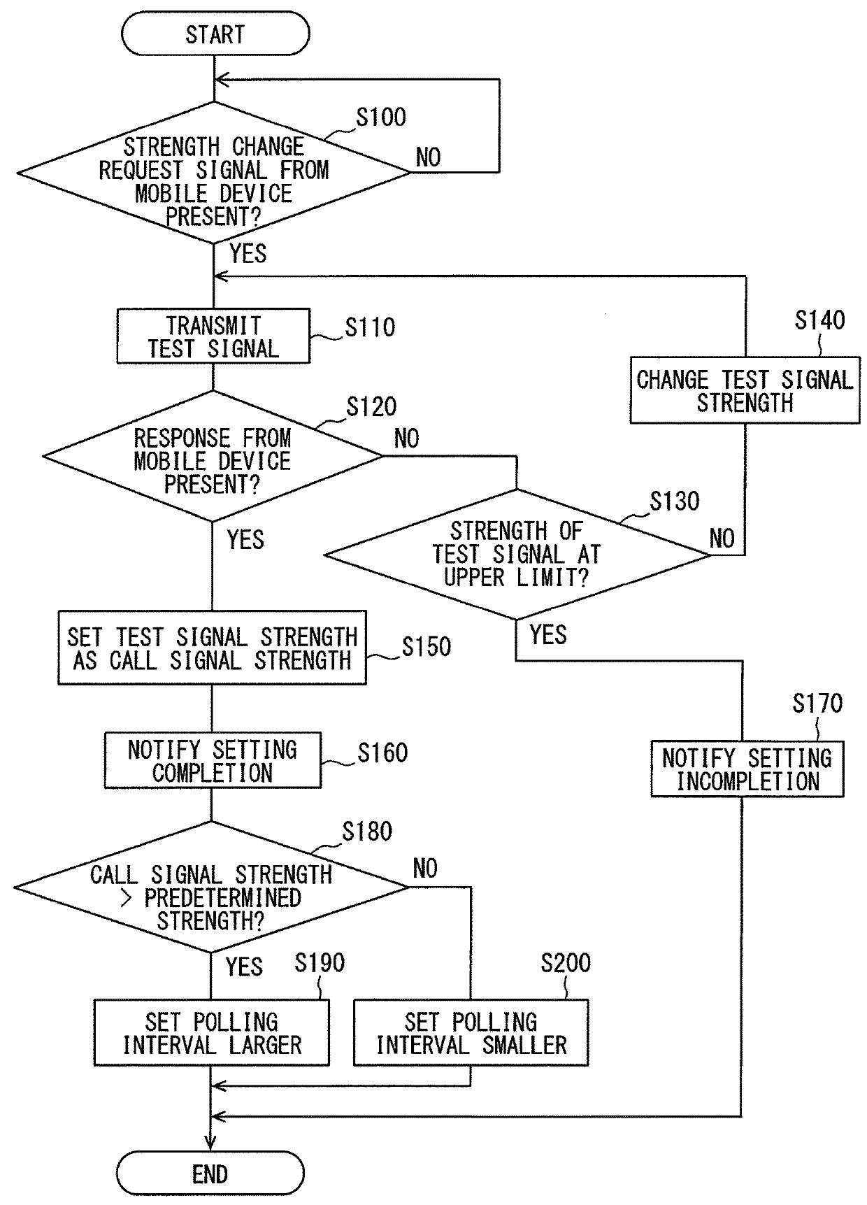
[0062]FIG. 3 shows a second embodiment. In the second embodiment, while the basic configuration of the smart entry system 100 is the same as in the first embodiment, the changing of the transmission interval of the call signal transmission based on the polling system in accordance with the output strength of the call signal is added to the control performed by the MPU 130.

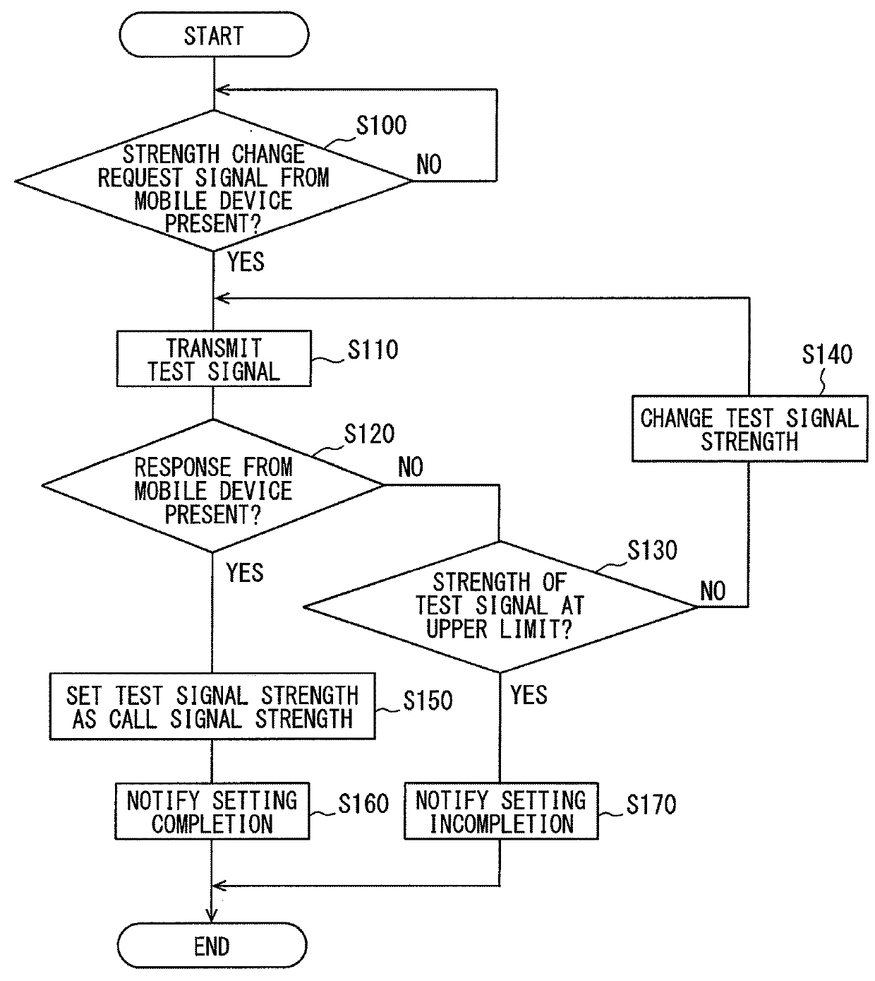
[0063]A flowchart shown in FIG. 3 is obtained by adding S180 to S200 to the flowchart illustrated in FIG. 2.

[0064]After the setting completion notification in S160, in S180 the MPU 130 determines whether or not the output strength of the changed and set call signal is larger than a predetermined strength. If Yes in S180, in S190 the MPU 130 (output strength setting unit 132) sets the transmission interval of the call signal based on the polling system to be larger than a transmission interval in the case of the predetermined strength.

[0065]If No in S180, in S200 the MPU 130 sets the transmi...


PUM


Abstract

A smart entry system that releases a lock of an opening / closing body includes: a transmission unit that transmits a call signal to a mobile key by wireless communication; a reception unit that receives a response signal from the mobile key responding to the call signal; and a control unit that outputs a call signal transmission command to the transmission unit, performs authentication of the response signal when the reception unit receives the response signal, and outputs a command for unlocking the opening / closing body based on a result of the authentication. The call signal is transmitted by a polling system. The control unit includes an output strength setting unit that changes and sets an output strength of the call signal.

Description

CROSS REFERENCE TO RELATED APPLICATIONS[0001]This application is a U.S. National Phase Application under 35 U.S.C. 371 of International Application No. PCT / JP2015 / 005183 filed on Oct. 13, 2015 and published in Japanese as WO 2016 / 063496 A1 on Apr. 28, 2016. This application is based on and claims the benefit of priority from Japanese Patent Application No. 2014-217566 filed on Oct. 24, 2014. The entire disclosures of all of the above applications are incorporated herein by reference.TECHNICAL FIELD[0002]The present disclosure relates to a smart entry system that releases a lock of an opening / closing body.BACKGROUND ART[0003]A smart entry system described in Patent Literature 1 for example is known as a conventional smart entry system. More specifically, the smart entry system in Patent Literature 1 includes a transmitter that transmits a call signal to a smart key by wireless communication, a receiver that receives a response signal from the smart key responding to the call signal, ...

Claims


Application Information

Patent Timeline
Patent Type & Authority Patents(United States)
IPC IPC(8): G05B19/00E05B81/78E05B49/00B60R25/24G07C9/00H01Q1/32
CPCE05B49/008B60R25/245E05B81/78H01Q1/3283G07C2009/00769B60R25/24G07C9/00309G07C2009/00357G07C2009/00388G07C2209/63G07C9/00817G07C2009/00825G08B21/18G08C17/02
Inventor ISHIKAWA, RYUSUKENAGAI, NOBUYOSHIUENO, KOJI
Owner DENSO CORP
Why Eureka
Try Eureka