X-ray generation tube, X-ray generation device including the X-ray generation tube, and X-ray imaging system

a technology of x-ray generation and x-ray imaging, which is applied in the direction of x-ray tube target materials, x-ray tube targets and convertors, and diaphragm/collimeters, etc., can solve problems such as prone to thermal damage, and achieve high output intensity, reduce thermal damage to the target, and high life characteristics

Active Publication Date: 2016-08-30
CANON KK
View PDF35 Cites 1 Cited by
  • Summary
  • Abstract
  • Description
  • Claims
  • Application Information

AI Technical Summary

Benefits of technology

[0010]It is an object of the present invention to provide an X-ray generation tube capable of reducing thermal damage to the target and emitting an X-ray with high output intensity. Further, it is another object of the present invention to provide an X-ray generation device and an X-ray imaging system, in which a target has high life characteristics and output power is high.

Problems solved by technology

The target of the X-ray generation tube is irradiated with the focused electron beam, and hence is apt to be thermally damaged at a region where current density distribution of the electron beam is largest.

Method used


Image

  • X-ray generation tube, X-ray generation device including the X-ray generation tube, and X-ray imaging system
  • X-ray generation tube, X-ray generation device including the X-ray generation tube, and X-ray imaging system
  • X-ray generation tube, X-ray generation device including the X-ray generation tube, and X-ray imaging system

Examples


first embodiment

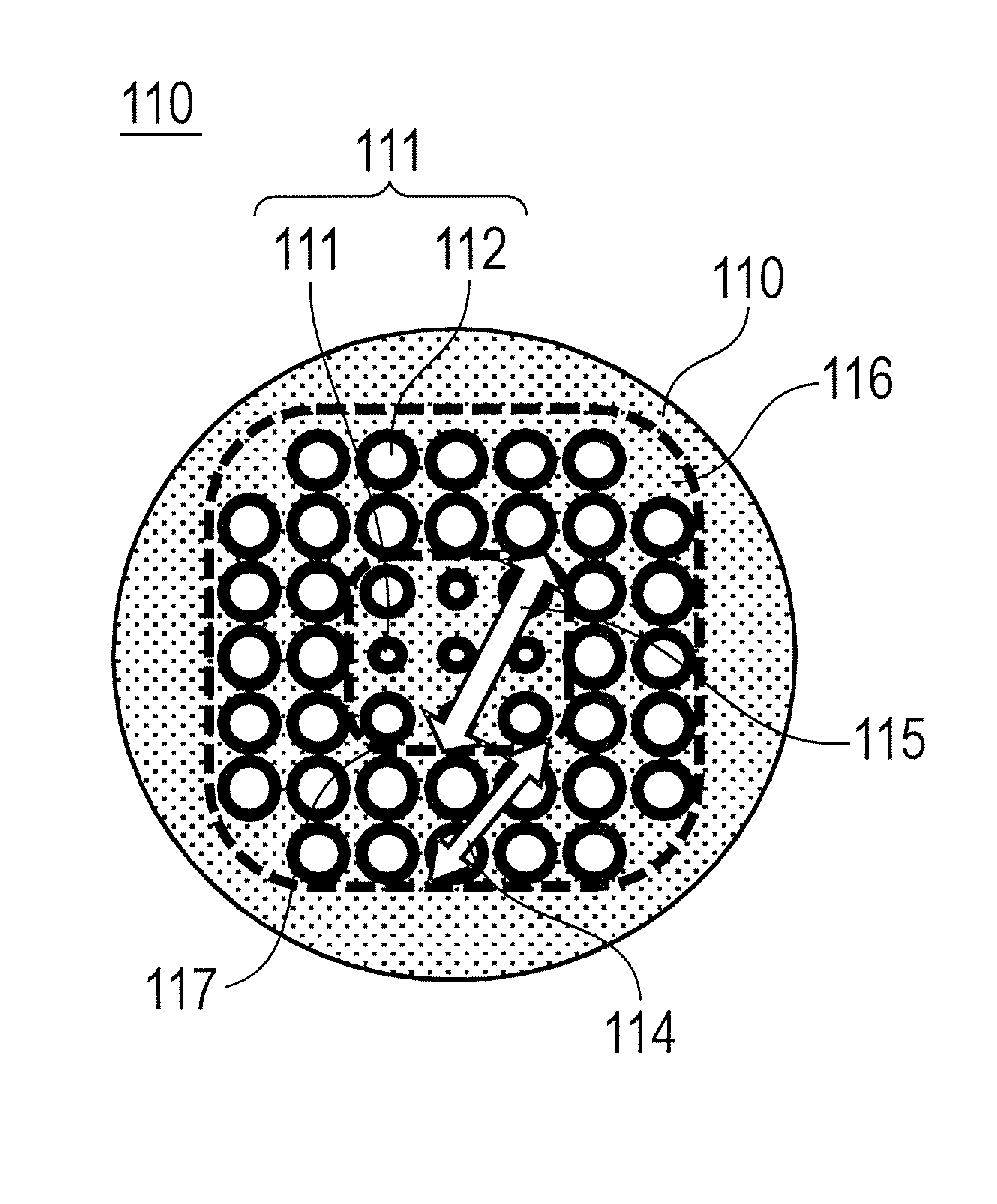
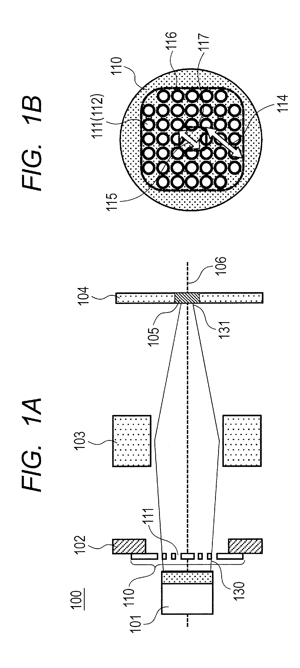
[0034]FIGS. 1A and 1B are diagrams illustrating an X-ray generation tube 100 according to a first embodiment of the present invention, and are schematic diagrams illustrating a layout of components necessary for describing the present invention. In FIG. 1A, an insulation tube constituting a barrel portion of the X-ray generation tube of this embodiment is omitted. An electron source 101 and an anode 104 constituting the X-ray generation tube 100 are fixed to the insulation tube (not shown).

[0035]In addition, the X-ray generation tube of this embodiment has a transmission type structure in which the X-ray is extracted from a surface opposed to an electron incident surface of a target 105, but the present invention can be applied to a reflection type X-ray generation tube.

[0036]In the grid electrode 210 of the X-ray generation tube 200 of the reference example described above, the electron passage apertures 211 are uniformly arranged as illustrated in FIG. 5B. Therefore, there is no d...

second embodiment

[0085]FIG. 6 illustrates an X-ray generation device 10 according to an embodiment of the present invention, from which an X-ray beam is extracted toward the front of an X-ray transmissive window 13. The X-ray generation device 10 of this embodiment includes, inside a housing container 11 that has the X-ray transmissive window 13, the X-ray generation tube 100 as the X-ray source and a driving circuit 5 for driving the X-ray generation tube 100.

[0086]The driving circuit 5 applies a tube voltage between the electron source and the anode of the X-ray generation tube 100 to form an acceleration electric field between the target 105 and the electron emitting portion. By appropriately setting the tube voltage in accordance with a thickness of the target layer and an element type of the target metal, it is possible to select a type of radiation necessary for imaging.

[0087]It is preferred that the housing container 11 for housing the X-ray generation tube 100 and the driving circuit 5 have ...

third embodiment

[0089]Next, with reference to FIG. 7, a structural example of an X-ray imaging system 1 including the X-ray generation tube 100 of the present invention is described.

[0090]A system control device 2 integrally controls the X-ray generation device 10 and a radiation detection device 6 for detecting an X-ray. A driving circuit 5 outputs various control signals to the X-ray generation tube 100 under control by the system control device 2. In this embodiment, the driving circuit 5 is housed together with the X-ray generation tube 100 in the housing container for housing the X-ray generation device 10, but may be disposed outside the housing container. The control signal output by the driving circuit 5 controls an emission state of the X-ray beam to be emitted from the X-ray generation device 10.

[0091]The X-ray beam emitted from the X-ray generation device 10 is radiated to the outside of the X-ray generation device 10 after the radiation range thereof is adjusted by a collimator unit (no...


PUM


Abstract

Provided is a high-output X-ray generation tube in which thermal damage to a target is reduced. The X-ray generation tube includes a target, an electron source, and a grid electrode having multiple electron passage apertures disposed between the target and the electron source. A source-side electron beam on the electron source side with respect to the grid electrode has a current density distribution, and the grid electrode has an aperture ratio distribution so that a region of the source-side electron beam in which a current density is largest is aligned with a region of the grid electrode in which an aperture ratio is smallest.

Description

BACKGROUND OF THE INVENTION[0001]1. Field of the Invention[0002]The present invention relates to an improvement of output power of an X-ray generation tube, an X-ray generation device, and an X-ray imaging system.[0003]2. Description of the Related Art[0004]An X-ray generation tube is an X-ray source that is used for an X-ray generation device in an application of a medical diagnosis or a nondestructive inspection such as a foreign matter inspection. The X-ray generation tube includes an electron gun for emitting an electron beam, an anode for accelerating electrons, and a target for generating an X-ray by a collision of the electrons. The target is electrically connected to the anode.[0005]It is known that, in order to obtain a predetermined analysis resolution, the X-ray generation device includes a grid electrode having an electrostatic lens action for a purpose of decreasing a focus diameter of the electron beam to be formed on the target.[0006]Japanese Patent Application Laid-O...

Claims


Application Information

Patent Timeline
Patent Type & Authority Patents(United States)
IPC IPC(8): H01J35/04H01J35/14G21K1/02
CPCH01J35/045H01J35/14G21K1/02H01J35/147H01J35/025H01J2235/081H05G1/06H01J35/116
Inventor TSUJINO, KAZUYAUEDA, KAZUYUKI
Owner CANON KK
Why Eureka
Try Eureka