Exhaust gas cleaning system for construction machine

Active Publication Date: 2010-04-15
HITACHI CONSTR MASCH CO LTD
View PDF8 Cites 32 Cited by
  • Summary
  • Abstract
  • Description
  • Claims
  • Application Information

AI Technical Summary

Benefits of technology

[0025]According to the present invention, since forced regeneration can be repeated more often than in the case that the start of forced regeneration is repeated each time the PM deposition level in the filter exceeds the deposition level existing before the regeneration is started, the filter can be regenerated before a large amount of PM becomes deposited, and th

Problems solved by technology

However, the regeneration occurs after a large amount of PM has been trapped by the filter, so this is likely to cause decreases in output due to exhaust gas pressure rises existing immediately before the regeneration is started.
In addition, in the method of computing the PM deposition level by sensing the differential pressure across the filter, the relationship between the differential pressure across the filter and the PM deposition level is not linear, and the PM deposition level is difficult to derive accurately by computing.
The same problem also occurs in

Method used


Image

  • Exhaust gas cleaning system for construction machine
  • Exhaust gas cleaning system for construction machine
  • Exhaust gas cleaning system for construction machine

Examples


Embodiment Construction

[0074]Hereunder, an embodiment of the present invention will be described with reference to the accompanying drawings.

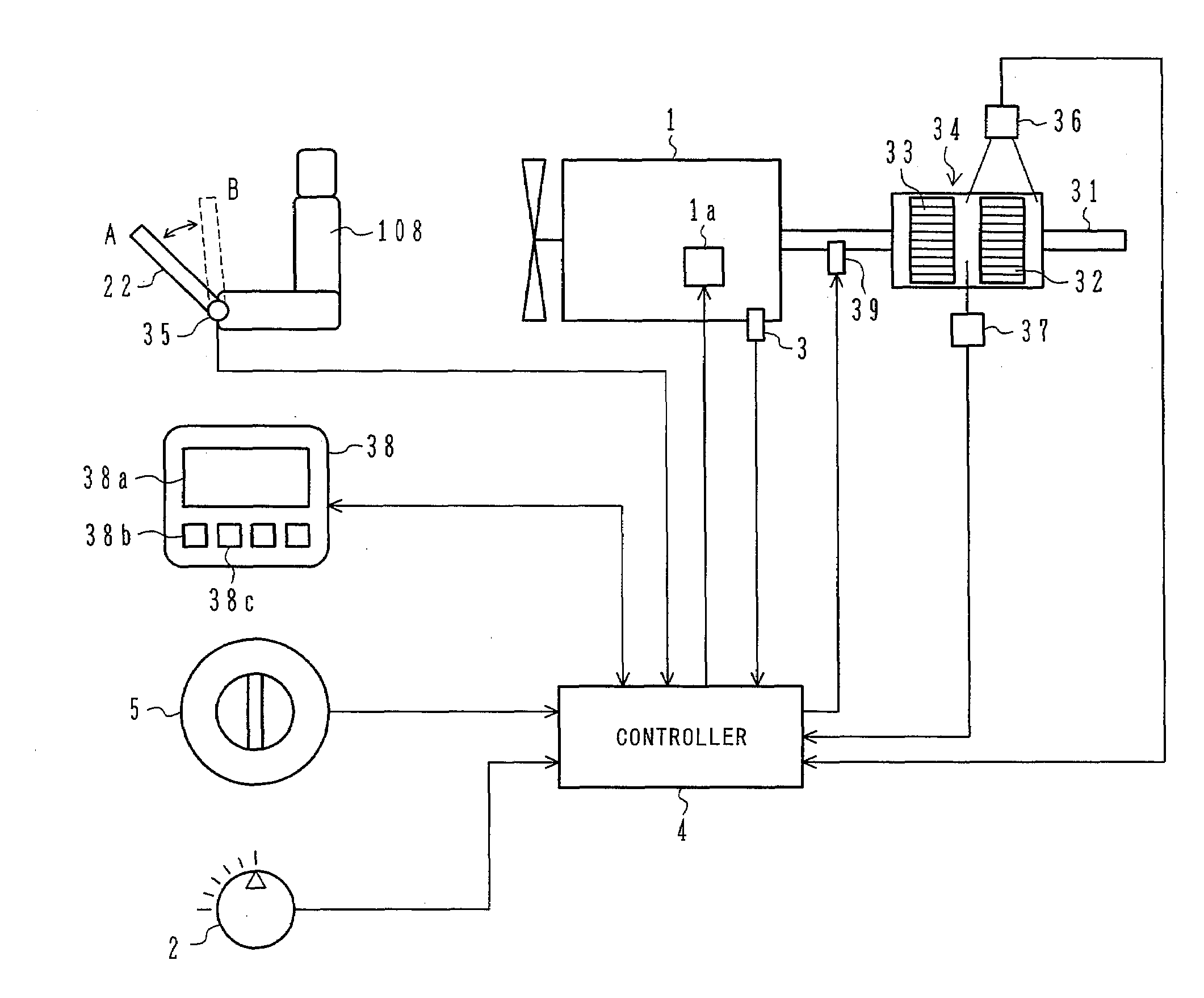
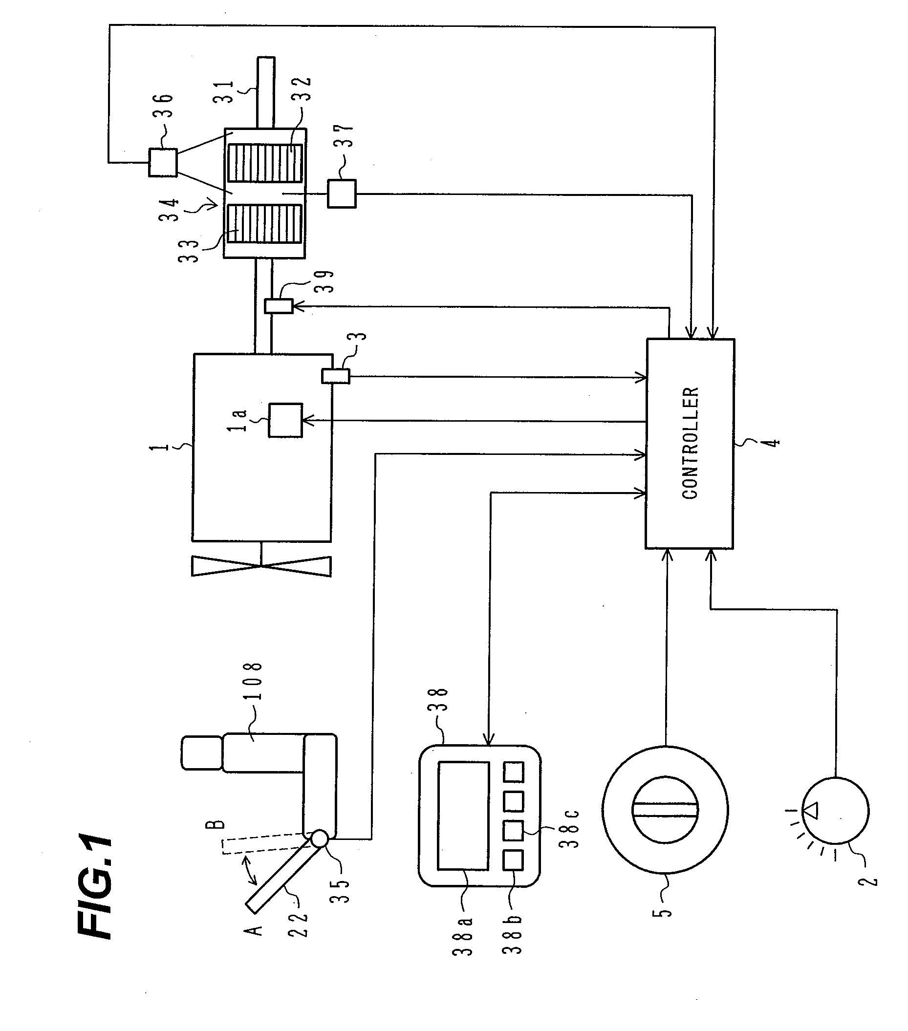
[0075]FIG. 1 is a total system block diagram showing an exhaust gas cleaning system for a construction machine according to an embodiment of the present invention.

[0076]Referring to FIG. 1, reference number 1 denotes a diesel engine mounted in the construction machine (e.g., a hydraulic excavator) that has the exhaust gas cleaning system of the present embodiment. The engine 1 includes an electronic governor 1a that is an electronic type of fuel injection control unit. A command specifying a desired rotating speed of the engine 1 is issued from an engine control dial 2, and an actual operating speed of the engine 1 is sensed by a speed sensor 3. The command signal from the engine control dial 2 and a sensor signal from the speed sensor 3 are input to a controller 4, which uses the command signal (target speed) and the sensor signal (actual speed) appropriately to con...


PUM


Abstract

Before a large amount of PM is deposited in a filter 32, an exhaust gas cleaning system for a construction machine regenerates the filter to avoid a decrease in output due to the exhaust gas pressure rise occurring immediately before the filter is regenerated, and to reduce the likelihood of unusual increases in the internal temperature of the filter due to the combustion of the PM, associated with the execution of the regeneration, and consequential thermal damage to the filter. If a value of a differential pressure across the filter 32 is greater than a predetermined pressure, a controller 4 conducts engine speed control to a predetermined rotating speed Na suitable for the regeneration, then enters forced regeneration automatically, and burns off the PM. When the sensed differential pressure decreases below a predetermined pressure, the regeneration is terminated automatically and the engine 1 is stopped.

Description

TECHNICAL FIELD[0001]The present invention relates generally to exhaust gas cleaning systems for construction machines. More particularly, the invention concerns an exhaust gas cleaning system for a construction machine, the system being intended to clean exhaust gases by filter-trapping any particulate matter included in the exhaust gases, and to regenerate the filter by burning off the filter-trapped particulate matter as appropriate.BACKGROUND ART[0002]Hydraulic excavators and other construction machines have a diesel engine as a driving source for the machine. Regulations on the amount of particulate matter (PM) emitted from the diesel engine are being strengthened each year along with those of NOx, CO, HC, and the like. Exhaust gas cleaning systems for trapping PM with a filter called the diesel particulate filter (DPF), and reducing the amount of PM emitted to the outside, are known to be effective under the increasingly stringent regulation situation (refer to Patent Document...

Claims


Application Information

Patent Timeline
IPC IPC(8): F01N11/00F01N3/023F01N9/00F01N3/035
CPCE02F9/00E02F9/0866F01N3/023F01N9/002F01N2560/08Y02T10/47F02B3/06F02D29/02F02D41/029F02D41/042F01N2570/10Y02T10/40F01N3/021F02D29/00
Inventor KAMIYA, SHOHEINAKAMURA, KAZUNORI
Owner HITACHI CONSTR MASCH CO LTD
Why Eureka
Try Eureka