
Laser soldering method

A soft soldering and laser technology, applied in laser welding equipment, welding equipment, welding equipment, etc., can solve the problems of large welding heat input, thermal damage of electronic components, lack of luster, etc., and achieve precise positioning and concentrated heating Effect

Inactive Publication Date: 2010-06-23
HANS LASER TECH IND GRP CO LTD
View PDF0 Cites 33 Cited by
  • Summary
  • Abstract
  • Description
  • Claims
  • Application Information

AI Technical Summary

Problems solved by technology

The melting points of several lead-free solders widely used at present are about 30°C to 40°C higher than the melting point of traditional Sn-Pb solders. The melting point is 20°C to 40°C, which leads to the peak soldering temperature of lead-free solder reaching above 250°C, which can easily cause thermal damage to electronic components
In addition, if manual welding is used, because the amount of tin is not easy to control, the size of the solder joints is uneven, and due to the large amount of welding heat input and the long welding time, the surface is thermally oxidized and dull

Method used


Image

  • Laser soldering method
  • Laser soldering method
  • Laser soldering method

Examples


Embodiment Construction

[0028] In order to make the object, technical solution and advantages of the present invention clearer, the present invention will be further described in detail below in conjunction with the accompanying drawings and embodiments. It should be understood that the specific embodiments described here are only used to explain the present invention, not to limit the present invention.

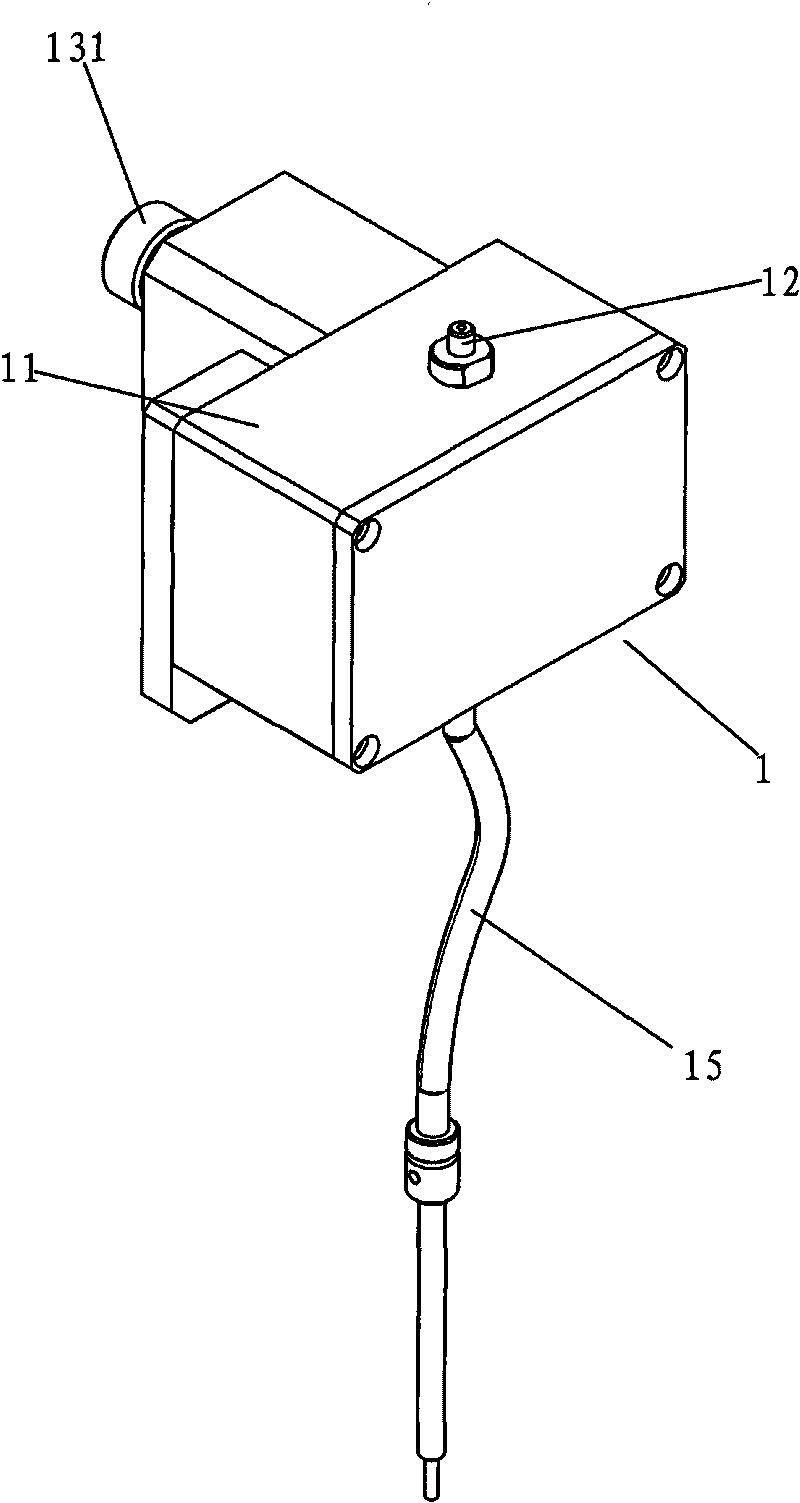
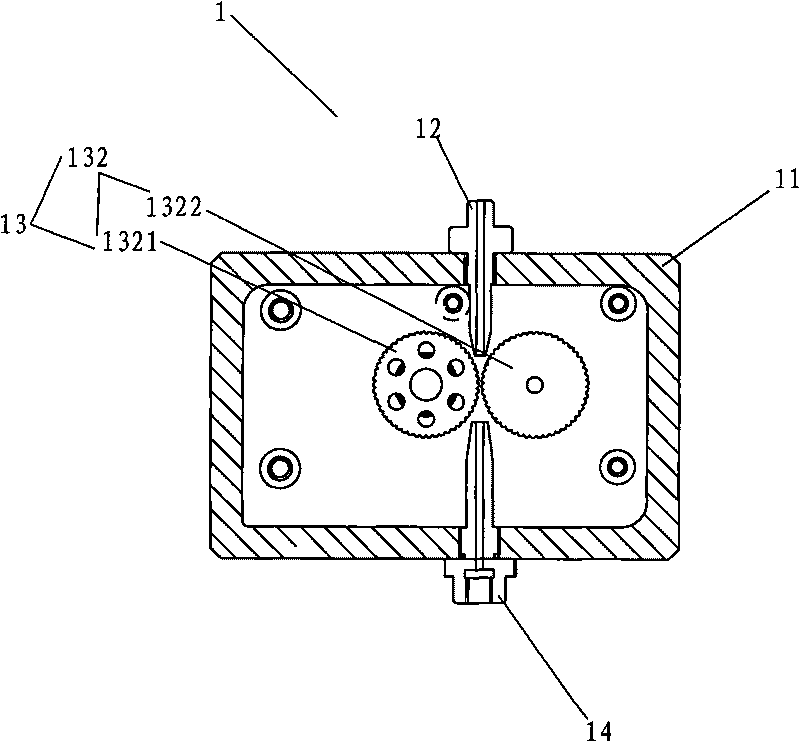
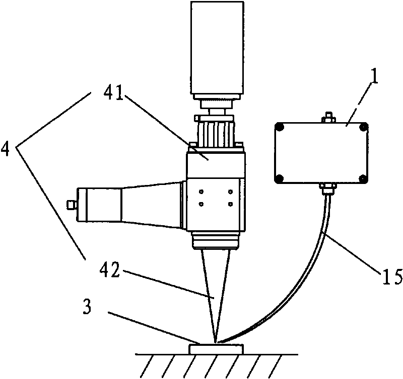
[0029] like figure 1 , 2 As shown, the present invention adopts a wire feeding mechanism 1 , which includes a housing 11 , a wire feeding nozzle 12 , a wire feeding device 13 and a wire outlet nozzle 14 .

[0030] During use, the rotation of the motor 131 is controlled by the single-chip microcomputer, thereby controlling the rotation of the gears 1321 and 1322. By adjusting the rotation speed and rotation angle of the motor, the wire feeding speed, wire feeding amount, interruption time, wire drawing speed, and drawing speed of the tin wire can be adjusted. The wire amount and other parameters a...


PUM


Abstract

The invention discloses a laser soldering method, comprising the following steps: (1) a semiconductor laser radiates a PCB pad with set energy so that the surface of the PCB pad reaches certain preheating temperature; (2) solder wires are fed to the surface of the PCB pad by a wire feeding mechanism on condition of certain feeding parameters; (3) under the action of laser radiation, the solder wires are molten and the molten tin spreads and moistens over the surface of the PCB pad; (4) the solder wires are withdrawn and removed from the pad; (5) the semiconductor laser continues radiating the pad so that the solder wires spread over the surface of the pad fully; and (6) the laser is closed and the tin is naturally cooled to form soldering points. During the use of the method, laser is used as soldering heat source, solder wires which are used as brazing filler metal are conveyed by wire feeder, and soldering connection is realized through the action of radiation of the laser to the tin wires and the PCB pad. Due to the characteristics of local heating, rapid heating, rapid cooling and the like during soldering, the method can effectively reduce heat loss of elements and greatly enhance the qualified rate of soldering.

Description

technical field [0001] The invention belongs to the field of brazing, and in particular relates to a laser soldering method using laser as a heat source and tin wire as solder. Background technique [0002] With the increasing awareness of human environmental protection, the use of lead-containing solder has been banned worldwide, which has brought many problems and challenges to the traditional assembly process of the electronics industry. The laser wire feeding welding process includes laser brazing, laser soldering and laser wire filling welding. The melting points of several lead-free solders widely used at present are about 30°C to 40°C higher than the melting point of traditional Sn-Pb solders. The melting point is 20°C to 40°C, which leads to the peak soldering temperature of lead-free solder reaching above 250°C, which can easily cause thermal damage to electronic components. In addition, if manual welding is used, the amount of tin is not easy to control, the size...

Claims


Application Information

Patent Timeline
IPC IPC(8): B23K1/005B23K26/20
Inventor 高云峰冷孝宇张勇刘维波王杨
Owner HANS LASER TECH IND GRP CO LTD
Learn More