Apparatus and method of generating laser beam

a laser beam and apparatus technology, applied in the direction of laser details, electrical apparatus, semiconductor lasers, etc., can solve the problems of increased laser cost, increased laser method, increased laser cost, etc., and achieve the effects of generating stably, simple apparatus structure, and excellent practicability

Inactive Publication Date: 2010-07-20
SUMITOMO OSAKA CEMENT CO LTD
View PDF8 Cites 1 Cited by
  • Summary
  • Abstract
  • Description
  • Claims
  • Application Information

AI Technical Summary

Benefits of technology

[0012]According to the laser and the method of generating a laser beam according to the invention, since a laser beam having a determined wavelength can be stably generated with a simple structure of the apparatus, it is possible to achieve excellent practicability with the low cost. Further, it is possible to achieve high output intensity of the laser beam.

Problems solved by technology

However, according to the method disclosed in Non-Patent Document 1, since a structure of the apparatus becomes complicated and a laser host material is high-priced, the cost of the laser is increased.
Accordingly, the method is not practical.
According to the method disclosed in Non-Patent Document 2, since two laser light sources are used, the cost of a laser is increased, and a structure of a driving power supply of an optical source becomes complicated.
Therefore, this method is also not practical.

Method used


Image

  • Apparatus and method of generating laser beam
  • Apparatus and method of generating laser beam
  • Apparatus and method of generating laser beam

Examples


example

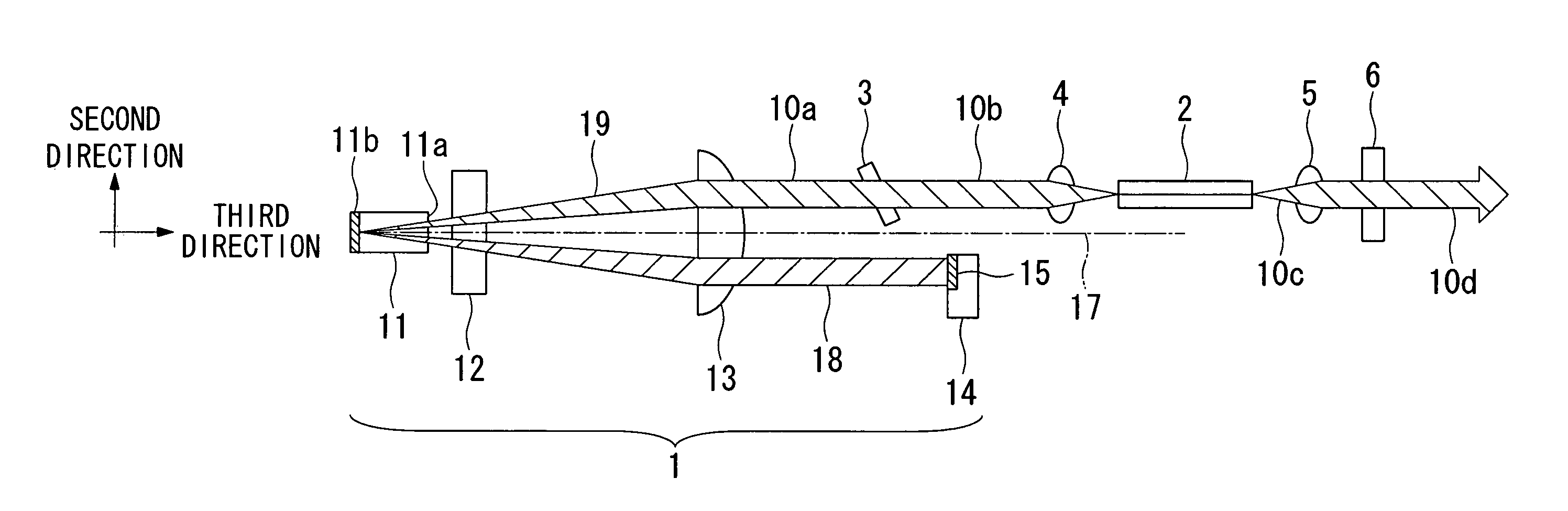
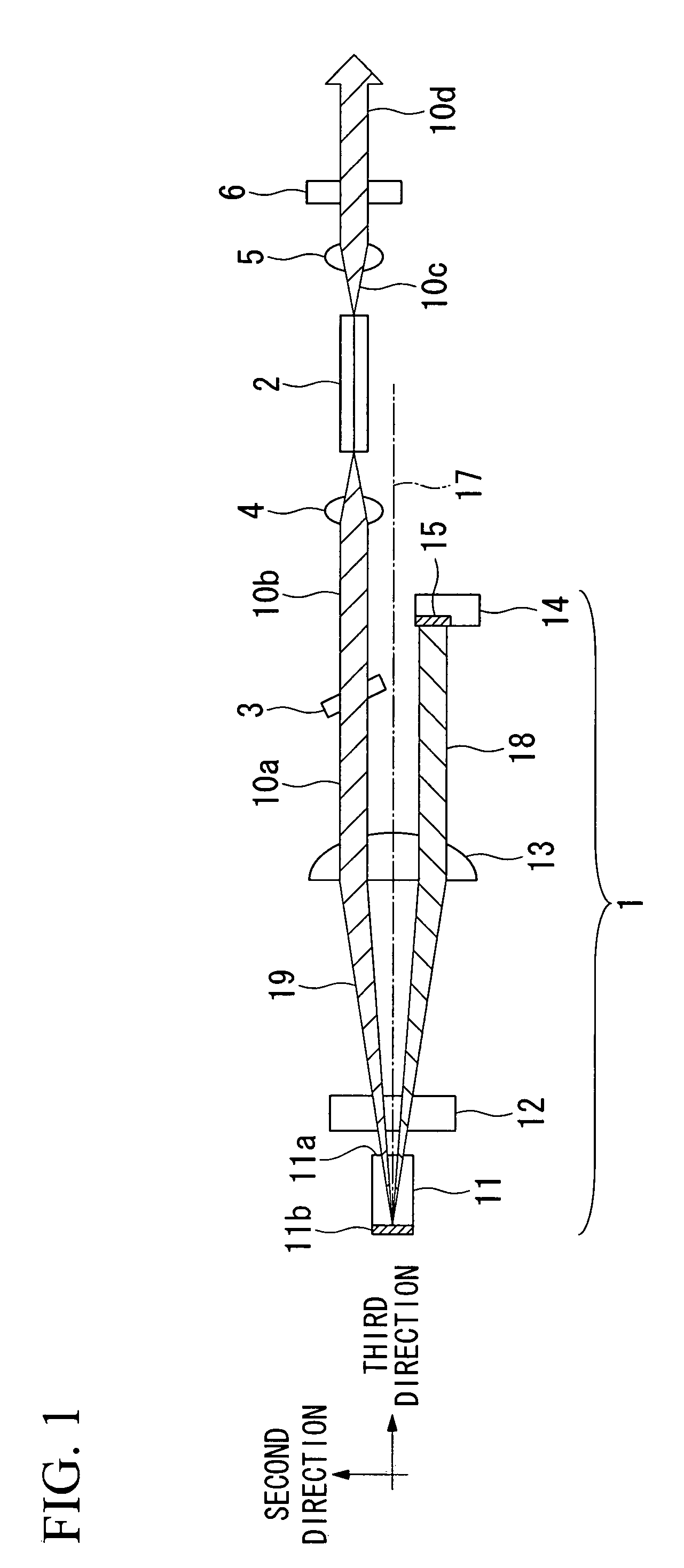
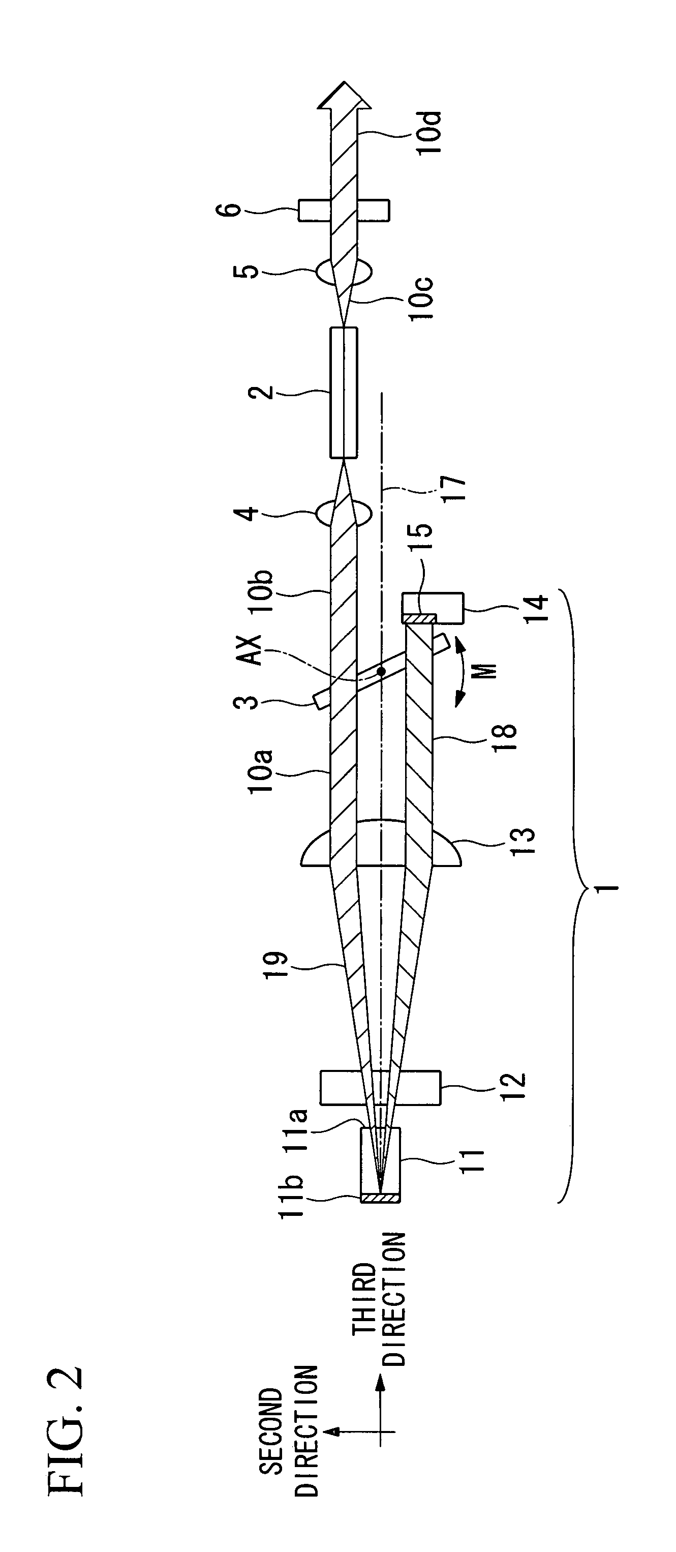
[0066]As an example, the laser that has the structure shown in FIG. 2 is manufactured.

[0067]In the semiconductor element 11, the BALD is used which includes a laser diode with gain waveguide layer and uses oscillation wavelengths of 1115 to 1125 nm.

[0068]As the first beam shaping element 12, an FAC is used which includes a cylindrical lens (optical fiber piece) having a diameter of 125 μm, a refraction index of 1.45, and a focal distance of 0.08 mm.

[0069]As the second beam shaping element 13, an SAC is used which includes an axis symmetric spherical lens having a focal distance of 20 mm.

[0070]As the reflective unit 14, a reflective mirror is used in which a region of the horizontal 3 mm× the vertical 3 mm is mirror-finished.

[0071]The distance between the semiconductor element 11 and the reflective unit 14 is set such that a resonance wavelength becomes 1120 nm.

[0072]As the third wavelength filter 3′, a light beam having a wavelength of 1120 nm is selectively transmitted by using a d...


PUM


Abstract

A laser beam generating apparatus includes a semiconductor element and a second harmonic generating element that performs a wavelength conversion on fundamental light emitted from the semiconductor element, the laser beam generating apparatus is an external resonance-type laser diode that has an external resonator structure and emits a transversal single mode laser beam, and the second harmonic generating element is a waveguide-type second harmonic generating element that includes a single mode waveguide.

Description

TECHNICAL FIELD[0001]The present invention relates to an apparatus and a method of generating a laser beam having a specific wavelength.[0002]Priority is claimed on Japanese Patent Application No. 2005-119048, filed Apr. 15, 2005, and Japanese Patent Application No. 2005-282455, filed Sep. 28, 2005, the contents of which are incorporated herein by reference.BACKGROUND ART[0003]As an example of a method of obtaining a laser beam of a deficient wavelength that cannot directly oscillate the laser beam from a gas-state laser, a laser diode (LD), and a solid-state laser, one method has been suggested in Non-Patent Document 1 to be described below. According to this method, oscillation light (having a wavelength of 1122 nm) from an LD pumped solid-state laser is caused to be incident on a second harmonic generating element as fundamental light so as to be subjected to a wavelength conversion, thereby obtaining a laser beam having a wavelength of 561 nm.[0004]Further, a method has been kno...

Claims


Application Information

Patent Timeline
Patent Type & Authority Patents(United States)
IPC IPC(8): H01S3/10
CPCH01S5/141H01S3/08036H01S3/08063H01S3/0815H01S3/109
Inventor OGURI, HITOSHIHARA, TOKUTAKAMURE, MASAHITOYATSUKI, MIKI
Owner SUMITOMO OSAKA CEMENT CO LTD
Why Eureka
Try Eureka