Dynamic sparkling lighting device

a lighting device and dynamic technology, applied in the direction of electrical appliances, etc., can solve the problems of aesthetically invasive, more burdensome and complex installation, and unsatisfactory use of lead glass crystals to achieve sparkling,

Active Publication Date: 2022-02-03
SIGNIFY HLDG BV
View PDF0 Cites 1 Cited by
  • Summary
  • Abstract
  • Description
  • Claims
  • Application Information

AI Technical Summary

Benefits of technology

[0016]The present invention seeks to provide a lighting device according to the aforementioned field of the invention that can produce dynamic sparkling or twinkling effects at least for stationary observers.

Problems solved by technology

In this case, however, the light source must be installed as a separate component, which is aesthetically invasive and more burdensome and complex to install.
However, use of lead glass crystals to achieve sparkling is not ideal.
The crystals are generally expensive and heavy, and mounting them into a panel in order to realise the solution described is far from trivial.
This allows the appealing aesthetic effect of spatially dynamic sparkling to be created in environments and scenarios where, for reasons of space or of aesthetics, it is not practical or desirable to provide both a luminaire for functional lighting in addition to a dedicated decorative unit for providing the sparkling effect.

Method used


Image

  • Dynamic sparkling lighting device
  • Dynamic sparkling lighting device
  • Dynamic sparkling lighting device

Examples


Embodiment Construction

[0038]It should be understood that the Figures are merely schematic and are not drawn to scale. It should also be understood that the same reference numerals are used throughout the Figures to indicate the same or similar parts.

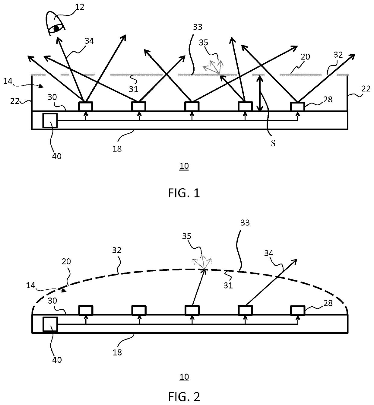
[0039]The invention provides a lighting device such as a luminaire configured to provide both functional lighting for illuminating a space, and simultaneously to present a spatially dynamic sparkling light display. The lighting device comprises a light mixing chamber containing one or more light sources. The light sources are arranged to direct light in the direction of a light diffusive surface, and in the direction of a plurality of light exit areas each delimited by a region of the light diffusive surface. The light exit areas each have a higher transmittance than the light diffusive surface regions.

[0040]Light incident at the light diffusive surface is transmitted from the lighting device at a higher level of attenuation than light incident at any of the ...


PUM

PropertyMeasurementUnit
timeaaaaaaaaaa
timeaaaaaaaaaa
timeaaaaaaaaaa

Abstract

A lighting device (10) is disclosed that comprises a light mixing chamber (14) at least partially delimited by a first surface (30) carrying a plurality of light sources (28) spatially distributed across said first surface and a second surface (31) arranged to be illuminated by said light sources, said second surface comprising light transmissive regions (33) delimiting light exit areas (32) having a higher light transmissivity than the light transmissive regions, said light transmissive regions exhibiting isotropic luminance and light exit areas exhibiting anisotropic luminance when illuminated by said light sources. The lighting device (10) further comprises a controller (40) adapted to individually control said light sources and having a mode of operation in which the controller is adapted to vary the luminous output of a selection of said light sources as a function of time such that the isotropic luminance of the light transmissive regions is time-independent and the anisotropic luminance of at least some of the light exit areas is time-dependent during said mode of operation.

Description

FIELD OF THE INVENTION[0001]The present invention relates to a lighting device comprising a light mixing chamber at least partially delimited by a first surface carrying a plurality of light sources spatially distributed across said first surface and a second surface arranged to be illuminated by said light sources, said second surface comprising light transmissive regions delimiting light exit areas having a higher light transmissivity than the light transmissive regions, said light transmissive regions exhibiting isotropic luminance and light exit areas exhibiting anisotropic luminance when illuminated by said light sources; and a controller adapted to individually control said light sources.BACKGROUND OF THE INVENTION[0002]The natural world provides many examples of so called dynamic lighting effects, and these phenomena can, for the observer, be highly captivating and entrancing aesthetic experiences. Consider, for example, sunlight refracted by water droplets or reflected on th...

Claims


Application Information

Patent Timeline
Patent Type & Authority Applications(United States)
IPC IPC(8): H05B47/155H05B47/16H05B47/17H05B45/10H05B45/20
CPCH05B47/155H05B47/16H05B45/20H05B45/10H05B47/17H05B45/44
Inventor VAN BOMMEL, TIESVAN DIJKEN, ALBERT
Owner SIGNIFY HLDG BV
Why Eureka
Try Eureka