Supercharge Your Innovation With Domain-Expert AI Agents!

Plug connector

a technology of plug-side connectors and connector elements, which is applied in the field of plug-side connector elements, can solve the problems of short-circuiting, damage to the pins and the shells of both connector elements, and the inability to remove the plug-side connector element from the receptacle-side connector element easily, so as to achieve accurate and secure connections or coupling between the connector elements. easy

Inactive Publication Date: 2012-10-30
APPLE INC
View PDF110 Cites 4 Cited by
  • Summary
  • Abstract
  • Description
  • Claims
  • Application Information

AI Technical Summary

Benefits of technology

The present invention provides an electrical connector that allows for easy and secure connections between connector elements without causing pin or electrode misalignment. The connector has a unique structure that includes an engagement projection on the first connector element and an engagement slit on the second connector element. When the two connectors are connected, the engagement slit engages with the engagement projection, guiding the second connector element and correcting any oblique posture as it is pushed into the first connector element. This ensures that the pins (electrodes) in both connectors are aligned straight and securely connected.

Problems solved by technology

If the plug side connector element in an oblique posture with reference to the receptacle side connector element, as shown in FIG. 10, is pushed into the receptacle side connector element, an irregular pin connection is made (as at 100) as seen from the enlarged view shown in the circle in FIG. 10, and this would cause several problems including short-circuiting.
In addition, when the plug side connector element is connected to the receptacle connector element in a slanted posture (which can easily occur when there is size differences between the receptacle and plug side connector elements), removing of the plug side connector element from the receptacle side connector element is not easily done and occasionally requires forcible and repeated twists on the shell of the plug side connector element This would cause damage to the pins and the shells of both connector elements.
Thus, though pin alignment is essential when connection is made between the two connector elements, such a pin alignment is not obtained easily and this difficulty can occur often when the connector is small in size and used in small size electrical devices such as a personal digital assistance (PDA), digital cameras, camcorders, etc.

Method used


Image

  • Plug connector
  • Plug connector
  • Plug connector

Examples


Embodiment Construction

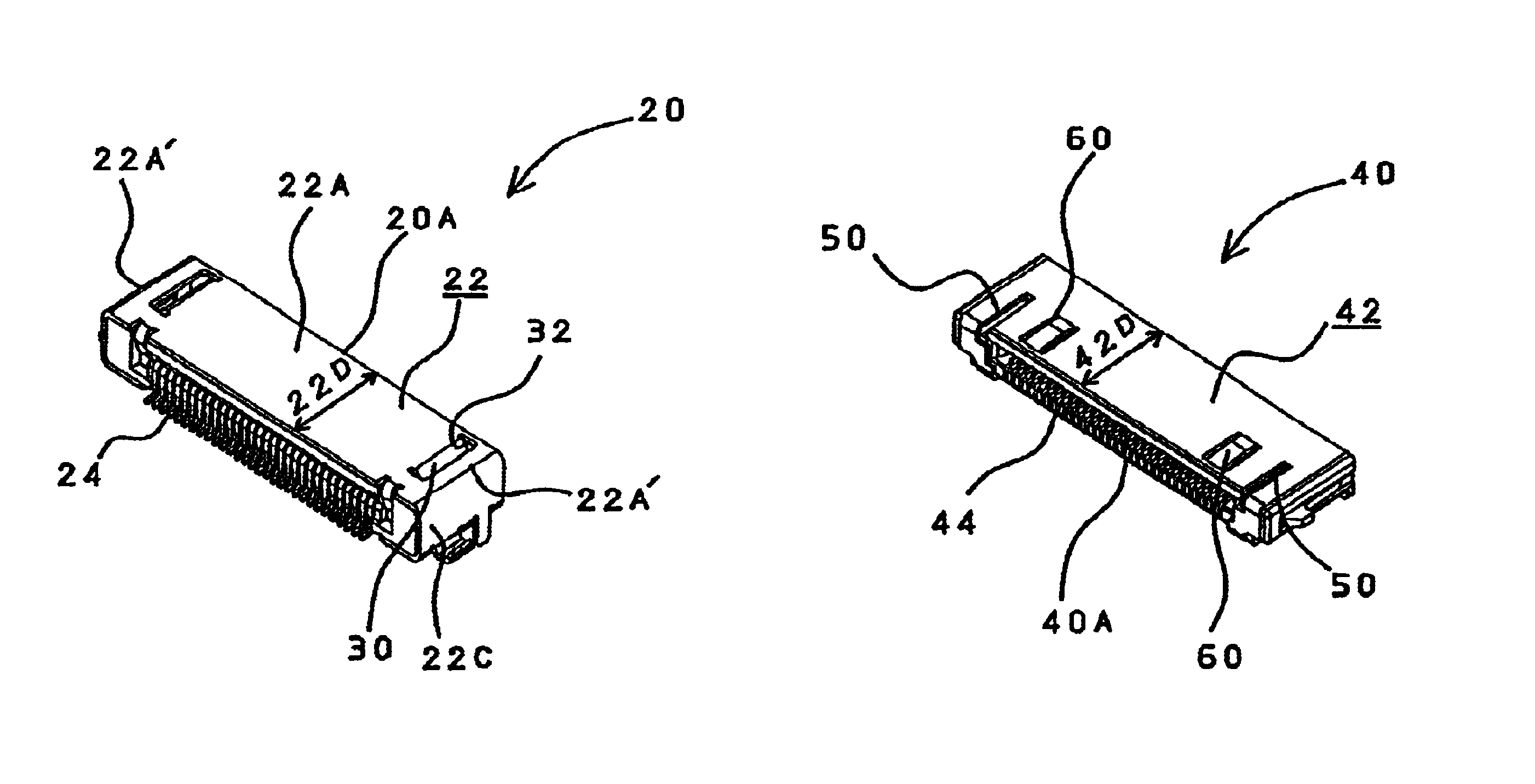
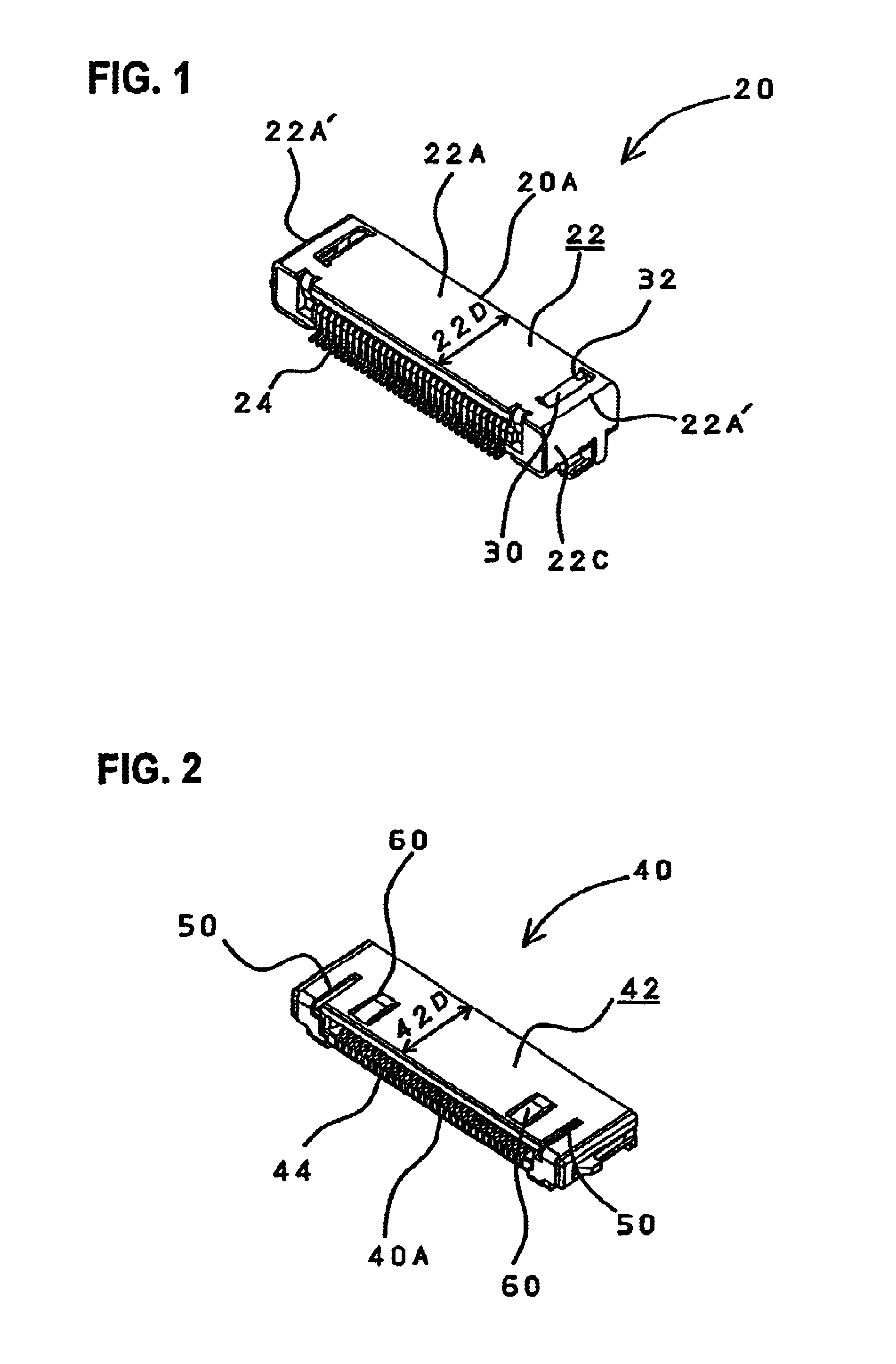
[0025]The connector of the present invention is comprised of a first connector body 20 (a receptacle side connector element) and a second connector body 40 (a plug side connector element).

[0026]As seen from FIGS. 1 and 2, the first and second connector bodies 20 and 40 comprise respectively a relatively flat box shape shell 22 and 42 made of a metal and include therein a plurality of pins or elongated electrodes, which are collectively referred to by the reference numerals 24 and 44 respectively, and an insulating material (not shown) is filled therein so as to positionally secure the pins 24 and 44.

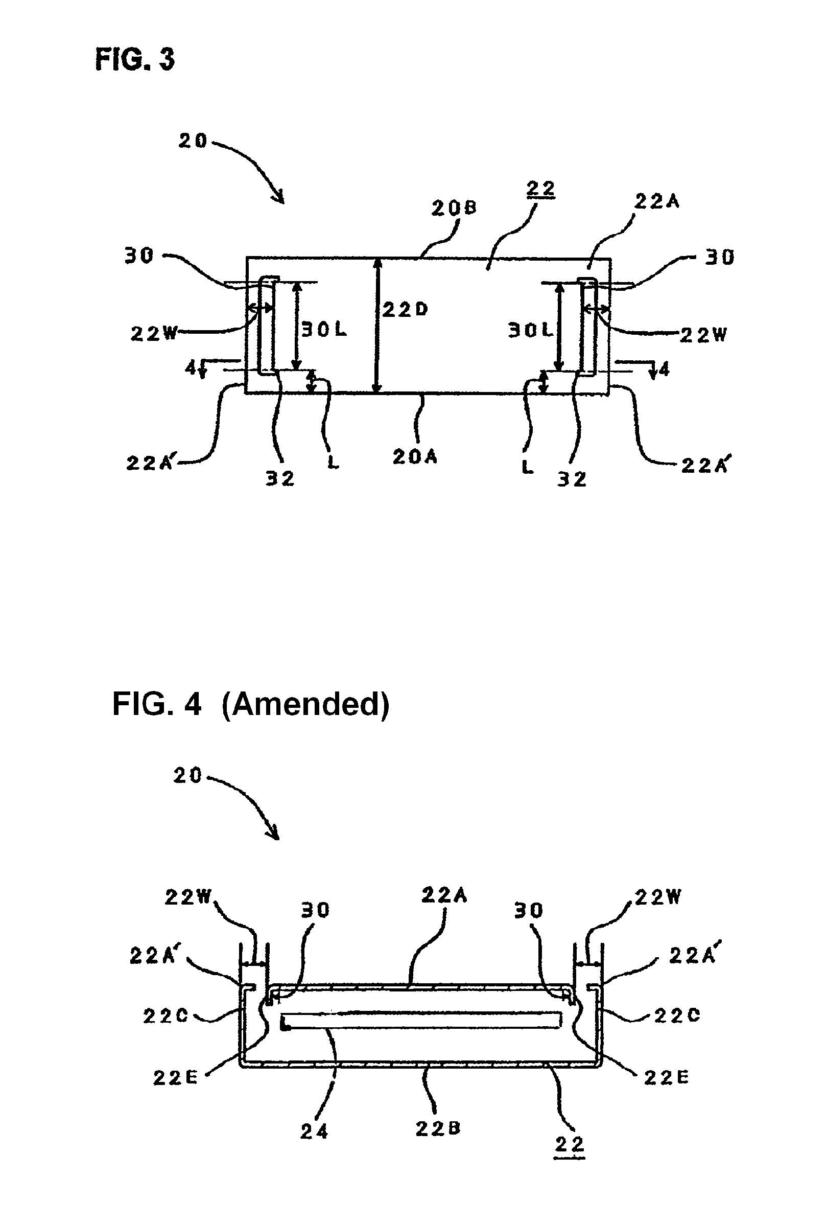
[0027]The shell 22 of the first connector body 20 comprises, as best seen from FIG. 4, a top shell plate 22A and a bottom shell plate 22B as well as side shell plates 22C, thus forming a box shape that has a predetermined depth 22D (see FIG. 3) that extends from the front edge 20A to the rear edge 20B of the first connector body 20. The pins 24 of the first connector body 20 are arranged...


PUM


Abstract

A connector including a first connector element and a second connector element that are coupled into a single unit, in which the first connector element has an engagement projection that projects interior of the first connector element and extends in the direction of the depth of the first connector element so that the front end of the engagement projection is spacedly apart from the front edge of the first connector element, and the second connector element is formed with an engagement slit that extends in the direction of depth of the second connector element and engages with the engagement projection of the first connector element.

Description

[0001]Notice: More than one reissue application has been filed for the reissue of U.S. Pat. No. 6,776,660. The reissue applications are application Ser. Nos. 11 / 334,820 and 29 / 318,045, all of which are continuation reissues of Ser. No. 11 / 334,820. BACKGROUND OF THE INVENTION[0002]1. Field of the Invention[0003]The present invention relates to a connector and more particularly to an electrical connector used in, for instance, small size electrical appliances.[0004]2. Prior Art[0005]In for instance, computer related electronic appliances, the electrical connections including connections to an AC adapter, to interfaces, etc. are made in many different ways. Such electrical connections are typically made by connectors that substantially comprise a receptacle (female) side connector element and a plug (male) side connector element that is brought into the receptacle side connector and coupled thereto for making electrical connection in between so that pin-shaped electrodes installed in t...

Claims


Application Information

Patent Timeline
Patent Type & Authority Patents(United States)
IPC IPC(8): H01R13/64H01R24/58H01R13/629H01R43/16
CPCH01R13/629H01R43/16H01R23/6873H01R12/75
Inventor KUBOTA, YOSHIFUMIKUROKI, YOSHIHIDEWATANABE, MASAHIDE
Owner APPLE INC
Features
  • R&D
  • Intellectual Property
  • Life Sciences
  • Materials
  • Tech Scout
  • Unparalleled Data Quality
  • Higher Quality Content
  • 60% Fewer Hallucinations
Learn More