Lighting apparatus

a technology of lighting apparatus and light fixture, which is applied in the direction of lighting and heating apparatus, fixed installation, free standing, etc., can solve the problems of occupying a relatively large space, affecting the lighting effect, so as to facilitate storage and transport of the same, and facilitate the effect of removing

Inactive Publication Date: 2013-07-16
ADESSO
View PDF10 Cites 1 Cited by
  • Summary
  • Abstract
  • Description
  • Claims
  • Application Information

AI Technical Summary

Benefits of technology

[0010]The object of this invention is to provide a lighting apparatus which includes a pair of light bulbs that can provide a lighting effect comparable to that of a halogen lamp with the same wattage as the light bulbs, and a lamp shade that can be easily detached from a containment member such that a plurality of the lamp shades can be stacked one over another to facilitate storage and transport of the same.
[0011]Another object of the present invention is to provide a lighting apparatus which has cord members concealed within a closed accommodating space of the lighting apparatus such that accidental touching thereof can be avoided.

Problems solved by technology

(1) There is only one socket member 12 in the conventional lighting apparatus for receiving a light bulb, such as an incandescent lamp. The light bulb accordingly provides a poor lighting effect. In case a halogen lamp is used, a better lighting effect can be achieved. However, the halogen lamp will raise the ambient temperature of the conventional lighting apparatus.
(2) The conventional lighting apparatus is bulky and therefore occupies a relatively large amount of space during storage and transport. Even though the lamp shade 15 can be detached relative to the upright post 110, the lamp shades 15 of several conventional lighting apparatus cannot be stacked one over another due to the presence of the retention members 150.

Method used


Image

  • Lighting apparatus
  • Lighting apparatus
  • Lighting apparatus

Examples


Embodiment Construction

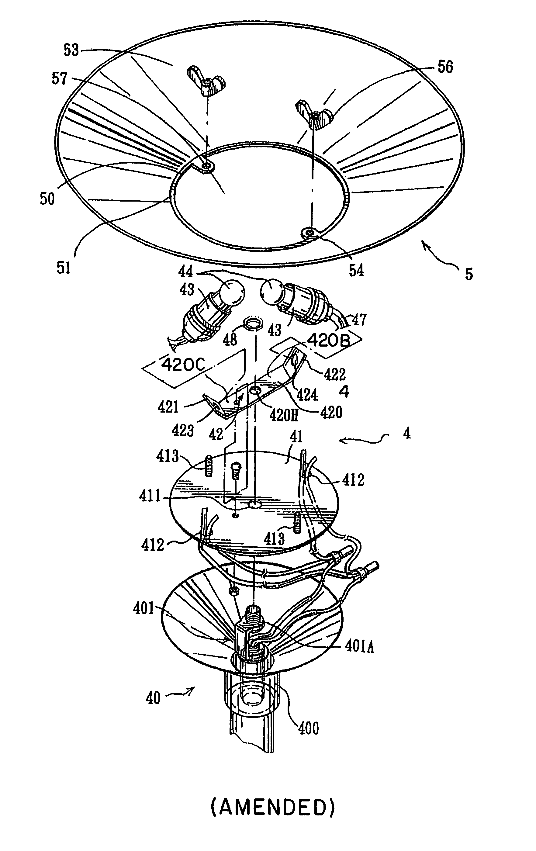
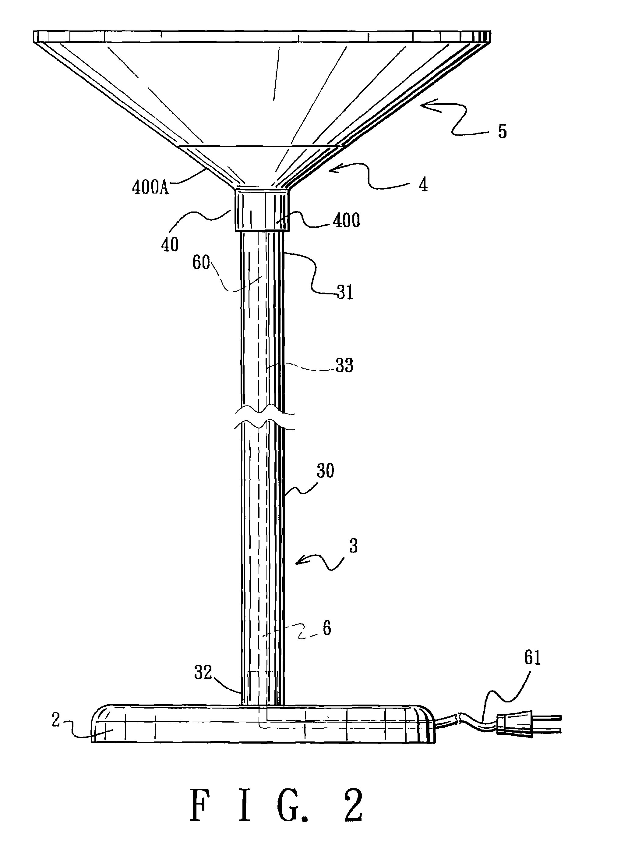
[0023]Referring to FIGS. 2, 3 and 4, the preferred embodiment of the lighting apparatus of this invention is shown to be embodied in a stand lamp that includes a support member 3, a lighting unit 4 mounted on the support member 3, and a lamp shade 5 mounted on the lighting unit 4. The lighting unit 4 includes a containment member 40, a mounting bracket 42, a pair of socket members 43, a pair of insulated conductive cord members 47, and a power cord member 6.

[0024]As illustrated, the containment member 40 has a mounting portion 400 mounted on the support member 3, a flared wall portion 400A extending from a periphery of the mounting portion 400 in a first direction away from the support member 3, and a partition plate 41 disposed inside the flared wall portion 400A in a second direction transverse to the first direction so as to define a closed accommodating space 45 on one side of the partition plate 41 proximate to the mounting portion 400, and an open accommodating space 46 on the...


PUM


Abstract

A lighting apparatus includes a support member, a lighting unit mounted on one end of the support member, and a lamp shade mounted on the lighting unit. The lighting unit includes a containment member having a mounting portion mounted on the support member, a flared wall portion extending from a periphery of the mounting portion in a first direction away from the support member, and a partition plate disposed inside the flared wall portion in a second direction transverse to the first direction so as to define a closed accommodating space and an open accommodating space on two sides of the partition plate. The partition plate is formed with a cord hole. A socket member is disposed in the open accommodating space for mounting a light bulb thereon. An insulated conductive cord member has a first end portion connected electrically to the socket member, and a second end portion that extends into the closed accommodating space via the cord hole in the partition plate. A power cord member has a first connecting end to be connected electrically with a power supply, and a second connecting end that extends into the closed accommodating space and that is connected electrically to the second end portion of the insulated conductive cord member.

Description

RELATED APPLICATIONS[0001]More than one reissue application has been filed for the reissue of U.S. Pat. No. 6,203,178. The present application is a continuation reissue application of U.S. Reissue patent application Ser. No. 10 / 365,627, filed on Feb. 12, 2003, entitled “LIGHTING APPARATUS” (reissue of U.S. Pat. No. 6,203,178 and now issued as Reissued U.S. Pat. No. Re. 39,810); which is a continuation-in-part, relates to, and claims priority from U.S. patent Ser. No. 09 / 012,362, filed on Jan. 23, 1998, entitled “LIGHTING FITTING,” now U.S. Pat. No. 5,980,071, issued on Nov. 9, 1999, and U.S. patent Ser. No. 09 / 042,212, filed on Mar. 13, 1998, entitled “LIGHTING FITTING,” now U.S. Pat. No. 6,004,012, issued on Dec. 21, 1999. FIELD OF THE INVENTION[0002]The invention relates to a lighting apparatus, more particularly to a lighting apparatus which has conductive cord members concealed within a closed accommodating space so as to provide safety when in use and which includes a lamp shad...

Claims


Application Information

Patent Timeline
Patent Type & Authority Patents(United States)
IPC IPC(8): F21S8/08F21S6/00F21V1/14F21V17/00F21V27/00
CPCF21S6/002F21V1/14F21V17/007F21V27/00
Inventor HSIEH, DUAN-CHENGSCHAAK, LEE
Owner ADESSO
Why Eureka
Try Eureka