Article surveillance unit and assemblies therewith

A technology for monitoring units and items, applied to electrical components, instruments, electrical alarms, etc.

Inactive Publication Date: 2007-12-12
B G PLASTICS
View PDF3 Cites 0 Cited by
  • Summary
  • Abstract
  • Description
  • Claims
  • Application Information

AI Technical Summary

Problems solved by technology

The disadvantage of this application on the outer surface is that although it is often covered by the barcode

Method used


Image

  • Article surveillance unit and assemblies therewith
  • Article surveillance unit and assemblies therewith
  • Article surveillance unit and assemblies therewith

Examples


Embodiment Construction

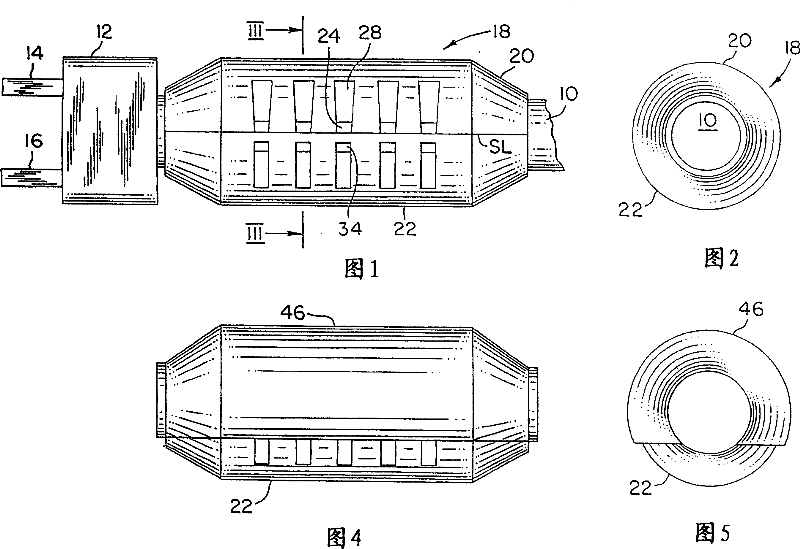
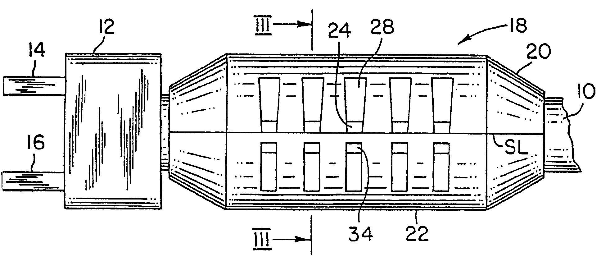
[0018] Referring to Figures 1-3, a cable assembly includes a cable 10 terminating in a plug 12 having conventional pins 14 and 16 . Assembled with the cable 10 is an item monitoring unit 18 . Unit 18 is made up of shell members 20 and 22 which are secured to each other along seam line SL.

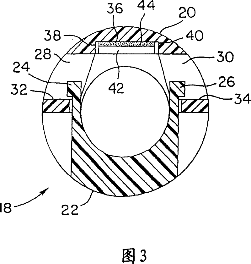
[0019] As seen in the cross-sectional view of FIG. 3, each housing member 20 and 22 defines a semicircular passage, and, when the housing members are fixed to each other, they jointly define a circular passage, the diameter of which accommodates the cable10. The housing member 22 includes fastening members 24 and 26 protruding upward therefrom. The housing member 20 has windows 28 and 30 which open to the periphery and which define fastening rails 32 and 34 at the bottom of the windows.

[0020] The housing member 20 defines a longitudinal recess formed therein and bounded by a top surface 36 and side walls 38 and 40 .

[0021] Upon reaching the assembly of FIG. 1 , the EAS member 42 is...


PUM


Abstract

An electrical cable assembly including an electrical cable (10) and an electrical connector (12) connected to the electrical cable has a housing (20,22) thereon defining a passage therethrough for the electrical cable and opposed housing ends circumscribing the cable, one of the housing ends being in facing relation to the electrical connector. The housing has an EAS member (42) secured therein aside the housing passage. An article surveillance unit has first and second housing members joined to one another and defining a seam line, one of the first and second housing members defining structure overlapping the seam line.

Description

technical field [0001] The present invention relates generally to measures to prevent theft of manufactured articles, and more particularly to electronic article surveillance (EAS) marking assemblies for use with manufactured articles. Background technique [0002] One widely used electronic article surveillance (EAS) marker is in the form of a flat, thin, flexible rectangular member that is glued to the flat or curved outer surface of the article. A disadvantage of this application on the outer surface is that, although often covered by the barcode label, the presence of the EAS mark is still evident because it can be seen from the side of the barcode label. In addition, the EAS tag can be accessed by customers. [0003] In commonly assigned US Patent No. 5,988,462, a clothes hook is disclosed which overcomes the above-mentioned disadvantages. Among them, a clothes hook is proposed, which is composed of a one-piece body, a middle part and a lower part. The body has a hoo...

Claims


Application Information

Patent Timeline
IPC IPC(8): H01R3/00G08B13/24
CPCG08B13/2402
Inventor 切斯特·科尔顿迈克尔·诺曼罗伯特·惠特莫尔
Owner B G PLASTICS
Why Eureka
Try Eureka