Transceiver/fiber optic connector adaptor with patch cord ID reading capability

a technology of patch cord and adapter, which is applied in the direction of optics, instruments, optical light guides, etc., can solve the problems of fiber optic cable being removed inadvertently from the host device, fiber optic cable no longer transmitting light energy to the host device, and the job of workers becoming very burdensome and time-consuming, etc., to facilitate the identification of a specific connector

Inactive Publication Date: 2007-06-05
STRATOS INT
View PDF22 Cites 215 Cited by
  • Summary
  • Abstract
  • Description
  • Claims
  • Application Information

AI Technical Summary

Benefits of technology

[0007]It is an object of the invention to provide a device which facilitates the identification of a specific connector or cable and to be able to retrieve information related to the life cycle of that specific connector or cable.
[0008]It is another object of the invention to provide a device which facilitates the identification of a specific connector or cable and to be able to retrieve warranty information related to that specific connector or cable.
[0009]It is yet another object of the invention to provide a device which facilitates the identification of a specific connector or cable and to be able to retrieve information related to the number of insertion cycles of the specific connector or cable.
[0010]It is still yet another object of the invention to provide a device which facilitates the identification of a specific connector or cable and to be able to retrieve information related to the number of rework instances.

Problems solved by technology

Experience has shown that a fiber optic cable can be inadvertently detached from the host device, or that the optical fiber within the fiber optic cable breaks and the fiber optic cable no longer transmits light energy to the host device.
When two or more fiber optic cables are malfunctioning, the worker's job becomes very burdensome and time consuming since there are hundreds of fiber optic cables to examine.
Furthermore, a device or person is not receiving information conveyed by the malfunctioning fiber optic cable.

Method used


Image

  • Transceiver/fiber optic connector adaptor with patch cord ID reading capability
  • Transceiver/fiber optic connector adaptor with patch cord ID reading capability
  • Transceiver/fiber optic connector adaptor with patch cord ID reading capability

Examples


first embodiment

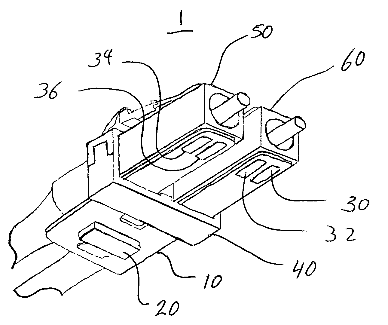
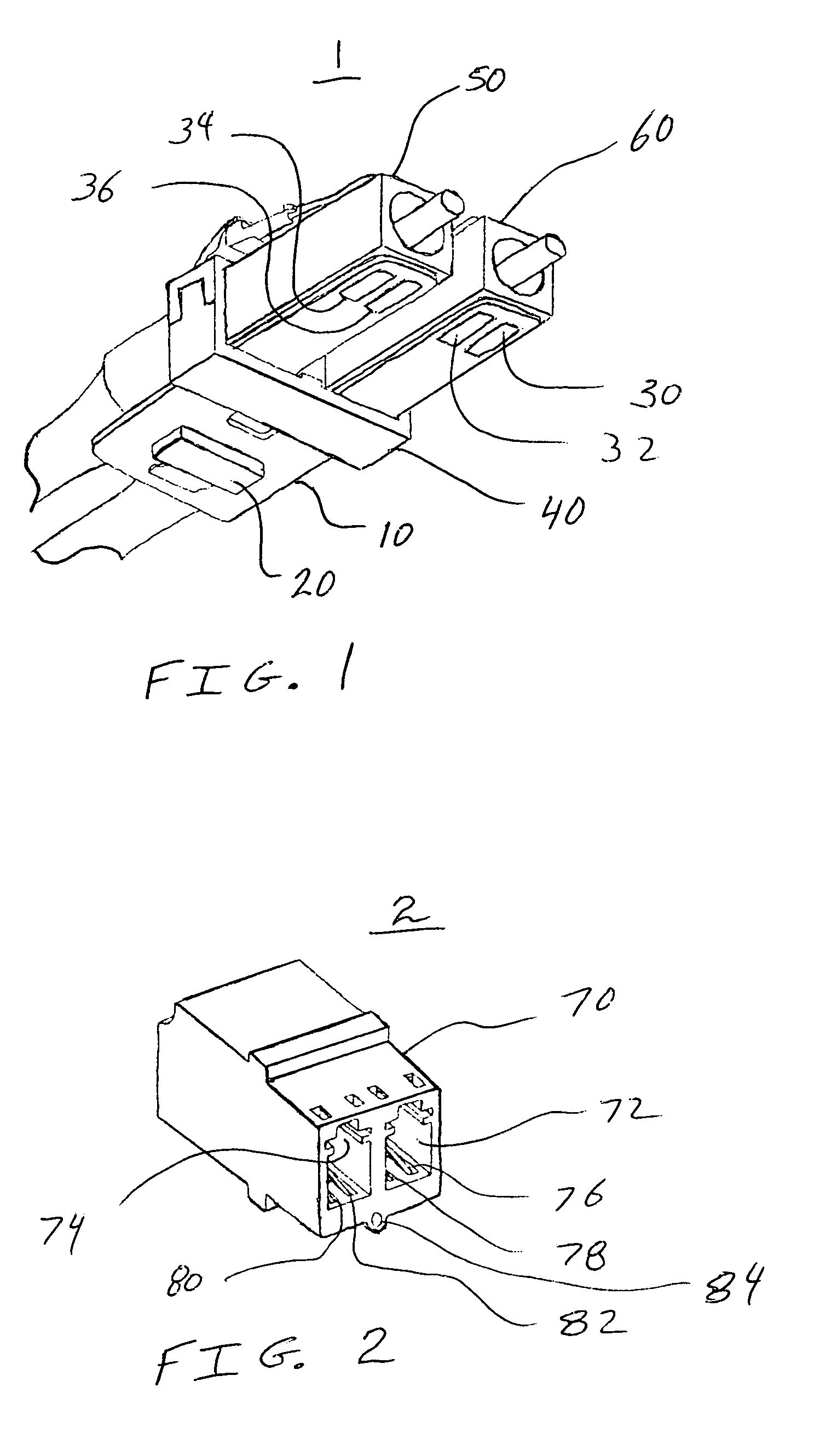
[0023]the invention is shown in FIG. 1. FIG. 1 is a perspective view of a hybrid connector or device 1 having both optical and electrical connector portions 50, 60, and 30, 32, 34, 36, respectively, and a memory chip 20. A flexible substrate 10, made of a polymer material, has conductive traces laid down on it so as to connect to the memory chip 20. The first electrical connector includes contacts 34, 36. The second electrical connector includes contacts 30, 32. The pairs of contacts 34, 36 and 30, 32 are electrically associated with the memory chip 20. The flexible substrate 10 can be mounted to the fiber optic connectors 50, 60 with an adhesive material. Additionally, or instead of the adhesive material, a clip 40 can be used to retain the first fiber optic connector 50 and the second fiber optic connector 60 adjacent to the flexible substrate 10. The use of the flexible substrate 10 allows existing fiber optic connectors to be retrofitted. U.S. Pat. No. 4,972,050 discloses a meth...

second embodiment

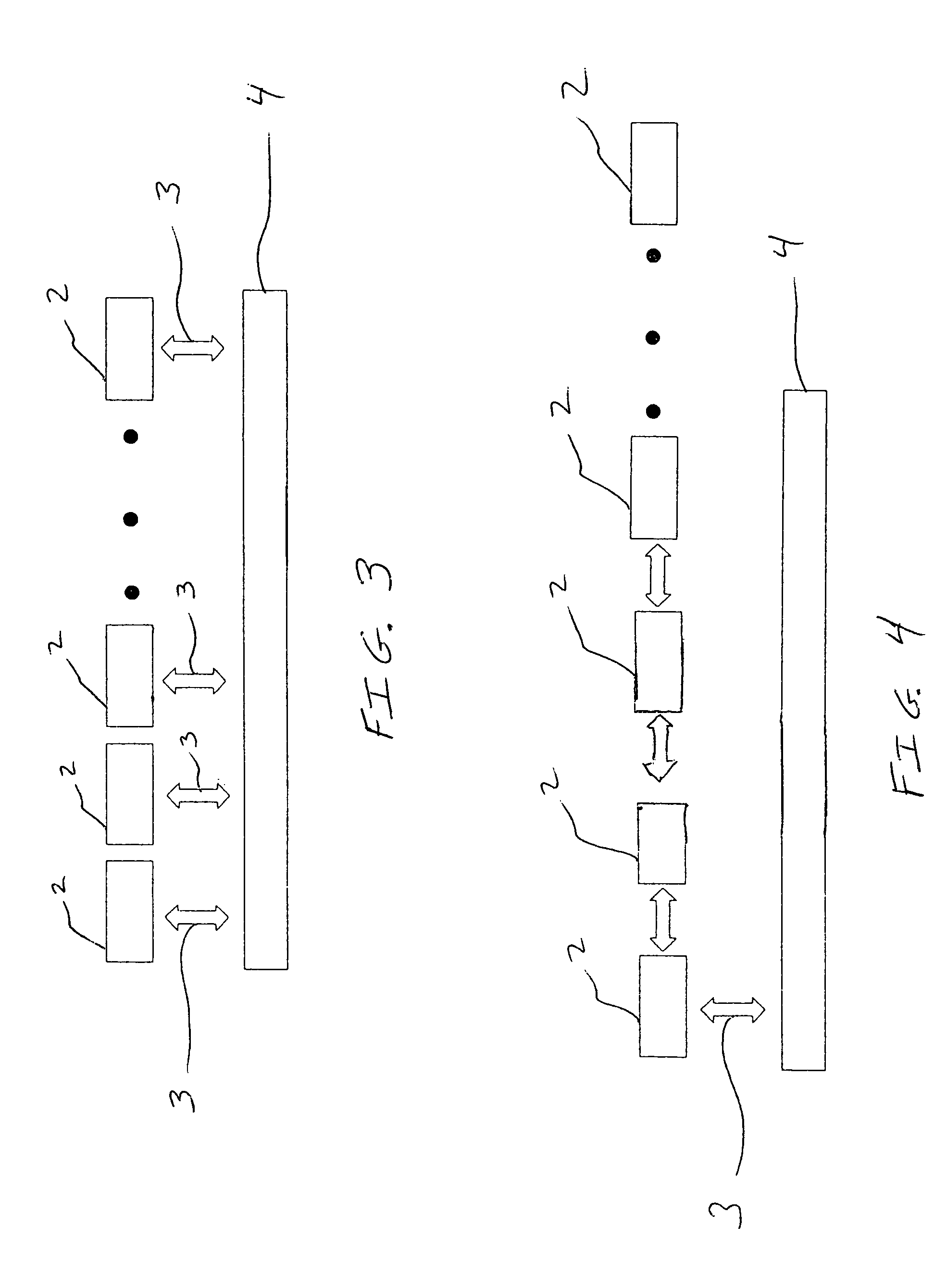
[0026]the invention is the combination of the hybrid connector 1, as shown in FIG. 1, and the adaptor 2, as shown in FIG. 2. FIG. 2 is a perspective view of another hybrid connector, or adapter, or coupler 2 having both optical and electrical connector portions that are complimentary to the optical and electrical connector portions of the hybrid connector 1 of FIG. 1. The adaptor 2 can be a stand alone device or it can be part of a patch panel where many of the adaptors are present adjacent to one another. Certain features of the adaptor, such as its optical interface, are similar to those features found on a transceiver, as is discussed later. The adaptor 2 includes a housing 70, a first optical connector 72 and a second optical connector 74. The first optical connector 72 is an LC standard receptacle that is designed to accept a fiber optic connector as shown in FIG. 1. The second optical connector 74 is an LC standard receptacle. The first optical connector 72 contains contacts 7...

third embodiment

[0034]the invention is shown in FIG. 5 which incorporates the adaptation of the contacts into the optical connector of a transceiver so as to make the connector a hybrid connector which enables the hybrid connector of the transceiver is compatible with the hybrid connector 1 of FIG. 1. FIG. 5 is perspective view of a transceiver 90 having a first optical connector 110, a second optical connector 120, contacts 91, 92 which form the first electrical connector, and contacts 93, 94 which form the second electrical connector. As is common to optoelectronic devices such as a transceiver, the device includes a first optical sub-assembly, a second optical sub-assembly, signal conditioning electronics, and a housing 130. The transceiver 90 includes a light emitting diode housing 95 which includes a first light emitting diode 96 and a second light emitting diode 97.

[0035]The shape and function of the first optical connector, the second optical connector, the first electrical connector, and th...


PUM


Abstract

The device includes a first optical connector, a second optical connector, a flexible substrate, a first electrical connector, a second electrical connector, a memory chip, and a clip. The first electrical connector is attached to the flexible substrate. The second electrical connector is attached to the flexible substrate. The memory chip is attached to the flexible substrate. A clip retains the first optical connector and the second optical connector adjacent to the flexible substrate.

Description

BACKGROUND OF THE INVENTION[0001]1. Field of the Invention[0002]The present invention pertains to hybrid connectors having optical and electrical connector portions. The invention more particularly concerns the management of a component or body, such as a hybrid connector, including the storage and updating of information related to events during the operational life of the component.[0003]2. Discussion of the Background[0004]Hybrid connectors are known the art. U.S. Pat. No. 5,473,715 discloses a hybrid connector having an optical connector portion conforming to the SC fiber optic connector standard and an electrical connector portion electrically associated with a small outline transistor. The small outline transistor contains an enhanced silicon serial number so as to uniquely identify the hybrid connector. The enhanced silicon serial number is placed on the small outline transistor by the manufacturer of the small outline transistor. The hybrid connector, once connected to a pat...

Claims


Application Information

Patent Timeline
Patent Type & Authority Patents(United States)
IPC IPC(8): G02B6/36
CPCG02B6/3825G02B6/3895G02B6/3879G02B6/4292
Inventor BENTON, MARKHERZING, BRIANKOWALKOWSKI, ANTHONY
Owner STRATOS INT
Why Eureka
Try Eureka