Electrostatic eliminator

A technology of static eliminator and discharge needle, applied in the direction of static electricity, electrical components, etc., can solve the problems of expensive, complex structure, electric shock accidents, etc.

Inactive Publication Date: 2007-12-19
株式会社高柳研究所
View PDF5 Cites 2 Cited by
  • Summary
  • Abstract
  • Description
  • Claims
  • Application Information

AI Technical Summary

Problems solved by technology

[0033] As described above, when a leakage occurs due to water droplets adhering to the high-voltage portion, the destaticizing function will be damaged and an electric shock accident will occur
[0034] (2) T

Method used


Image

  • Electrostatic eliminator
  • Electrostatic eliminator
  • Electrostatic eliminator

Examples


Embodiment Construction

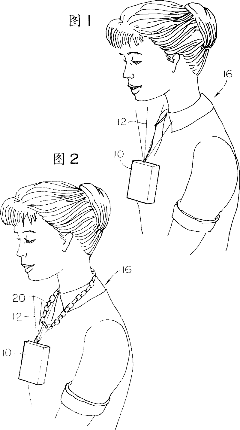
[0103] In FIG. 1 , a wearable or wearable static electricity removal instrument or tool that an operator can wear on his chest is shown. The static eliminator 10 worn by the operator 16 on his chest has an ionizing function, and the ions generated by the static eliminator are adapted to be sprayed or discharged to his face or neck. As a result, static electricity charged on the operator's body 16 is removed through his skin.

[0104] As for a modified embodiment shown in FIG. 2, the static eliminator 10 worn by the operator on his chest is adapted to spray ions onto a conductive body 20, such as a necklace he wears. Static electricity charged or accumulated on the operator's body 16 is removed or discharged to the air through the conductor 20 .

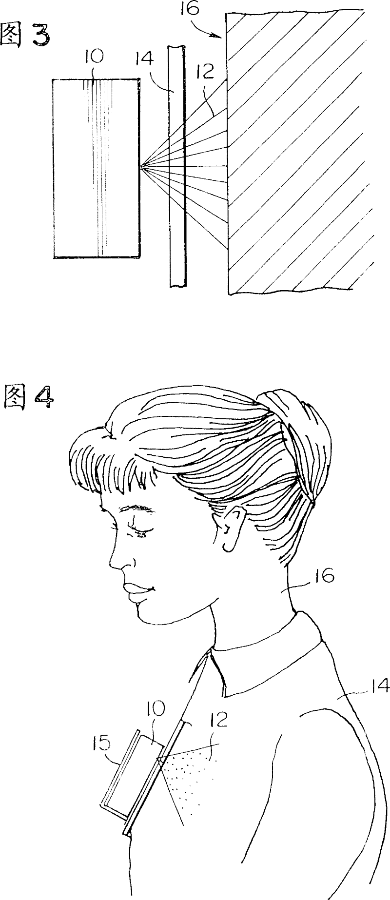
[0105] Fig. 3 shows an embodiment in which clothing exists between the operator's body and the static eliminator. In this case, the ions 12 pass through the clothing 14 to the skin of the operator's body 16 to remove static electric...


PUM


Abstract

There is a wear-type of static eliminator which comprises a static eliminator body, and a discharge section. Also there is a static potential measuring instrument which comprises: a plus discharge needle, a minus discharge needle, a current source, a plus current ammeter, a minus current ammeter, means of calculating the difference between absolute values of currents obtained by said ammeters, the ratio of one absolute value of current obtained by one of said ammeter to the other absolute value of current obtained by the other of said ammeter or both the difference and the ratio, and a measuring terminal.

Description

technical field [0001] The invention relates to a static eliminator. Background technique [0002] In industrial fields in which semiconductors are handled or surface treatments such as coating, plating, or evaporation are performed, static electricity as a harmful substance is eliminated or removed. A conventional static eliminator or removal instrument or tool, hereinafter referred to as a static eliminator, will be explained below. [0003] (1) Ionizer: [0004] The ionizer ionizes the air and ejects or expels ions. Ionizers are mounted to machines to neutralize or remove static electricity from workpieces, or are held and moved by an operator to remove static electricity from workpieces. In the former case, the workpiece is placed on the table on which the ionizer is mounted, and the ionizer is caused to discharge ions to the workpiece and remove static electricity from the workpiece. In the latter case, the operator holds the ionizer in order to direct ions from the...

Claims


Application Information

Patent Timeline
IPC IPC(8): H05F3/04H05F1/00
CPCH05F3/04H05F1/00
Inventor 高柳真
Owner 株式会社高柳研究所
Why Eureka
Try Eureka