Microkeratome cutting blade assembly and method for making the same

A microkeratome and cutting blade technology, applied in ophthalmic surgery and other directions, can solve problems such as difficulty, difficulty in adequately correcting patients' vision, and difficulty in detecting corneal flap thickness.

Inactive Publication Date: 2007-12-26
BAUSCH & LOMB INC
View PDF5 Cites 0 Cited by
  • Summary
  • Abstract
  • Description
  • Claims
  • Application Information

AI Technical Summary

Problems solved by technology

Conversely, if the corneal flap is too thin, the flap will be prone to rupture, or it will be difficult to correct the patient's vision adequately without complications such as halos
[0009] While corneal pachymetry is readily available prior to LASIK surgery, it has proven particularly dif

Method used


Image

  • Microkeratome cutting blade assembly and method for making the same
  • Microkeratome cutting blade assembly and method for making the same
  • Microkeratome cutting blade assembly and method for making the same

Examples


Embodiment Construction

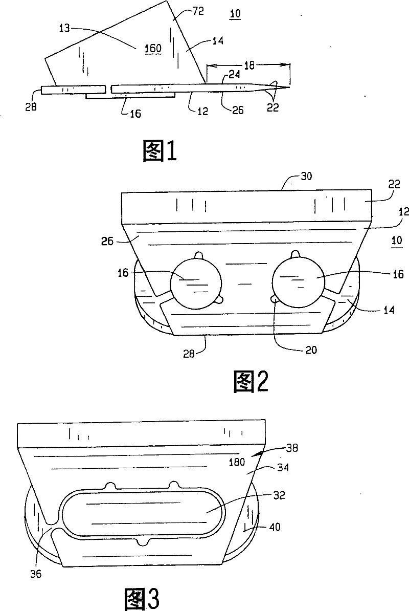
[0039] Figure 1 shows a microkeratome cutting blade assembly 10 of the present invention. The assembly 10 includes a cutting blade 12 and a blade holder 14 connected to the cutting blade 12 . Cartridge 14 is preferably attached to cutting blade 12 by post members 16 passing through apertures or through holes (not shown) in cutting blade 12 using known methods such as heat staking. However, other joining means such as cold staking, use of adhesives or other means are also possible. Also, the apertures need not be through holes as is known, but can be matching indentations and protrusions in the cartridge and blade. The difference between this assembly 10 and prior art assemblies is that the blade extension indicated by numeral 18 is controlled within a tolerance of at least 0.016 millimeters (six ten thousandths of an inch) to help and provide consistent, precise flap thickness. Such tight tolerance and blade extension have hitherto been unknown. For example, in the prior a...


PUM


Abstract

A microkeratome cutting blade assembly (10) includes a cutting blade (12) attached to a blade holder (14). A blade extension (18) is controlled to within at least six (6) ten-thousandths of an inch of a tangent extension length.

Description


Claims


Application Information

Patent Timeline
Owner BAUSCH & LOMB INC
Why Eureka
Try Eureka