Switch device

A technology of switch devices and components, applied in the direction of contact operating parts, etc., can solve the problems of aggravating the operating feeling and large sliding contact resistance, etc.

Inactive Publication Date: 2008-01-02
KK TOKAI RIKA DENKI SEISAKUSHO
View PDF3 Cites 0 Cited by
  • Summary
  • Abstract
  • Description
  • Claims
  • Application Information

AI Technical Summary

Problems solved by technology

[0006] In the above-mentioned conventional device, the structure is such that the sliding contact portion 3 on the support member side and the sliding contact portion 2 on the operating element side are in sliding contact at a position separated from the shaft support portion, so the resistance of the sliding contact is large and excessively aggravated. Operating sense

Method used


Image

  • Switch device
  • Switch device
  • Switch device

Examples


Embodiment Construction

[0019] Next, an example (an embodiment) of the present invention will be described with reference to FIGS. 1 to 4 .

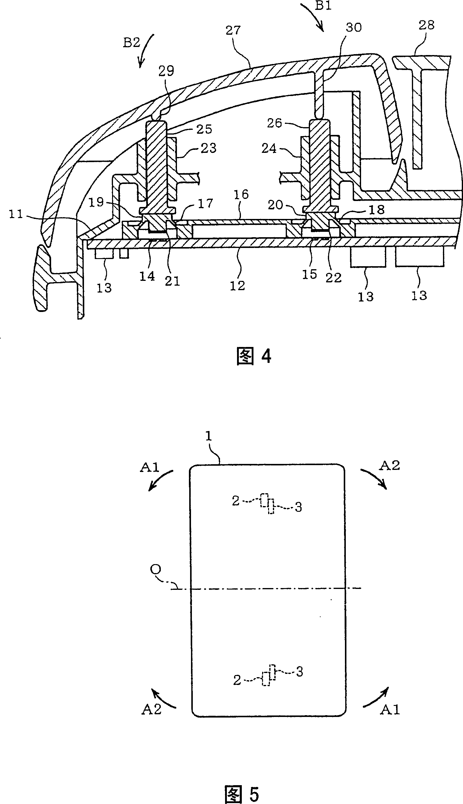
[0020] First, FIG. 4 shows the switch main body 11, and the circuit board 12 is assembled on the lower side thereof. Several circuit components 13 are mounted on the circuit board 12, and fixed contacts 14, 15 are separately provided on the front and back (left and right in FIG. 4) on the upper surface. In addition, the circuit board 12 is covered with an elastic sheet 16 made of an elastic material such as rubber, and the elastic sheet 16 forms a contact seat on the above-mentioned fixed contacts 14, 15 via thin bendable parts 17, 18, respectively. 19 , 20 , there are movable contacts 21 , 22 respectively facing the above-mentioned fixed contacts 14 , 15 on the lower surfaces of the contact bases 19 , 20 .

[0021] The switch main body 11 has a push rod guide rail 23,24 on the contact seat 19,20 respectively, so that each lower end of the push rod 25,26 inser...


PUM


Abstract

A sliding contact part 38 is provided at a peripheral part near a journal portion 32 of a switch body (supporting member) that journals the operator 27 in a rockable manner or a peripheral part near a portion of the operator 27 corresponding to the journal portion 32 so as to come in sliding contact with the counterpart as the operator 27 rocks. It is thereby possible to control the tilt of the operator 27 near the journal portion 32 of the supporting member or near the portion of the operator 27 corresponding to the journal portion 32. Thus, the sliding contact resistance is made smaller to make the operation feeling lighter.

Description

technical field [0001] The invention relates to a switch device composed of a swinging operating element. Background technique [0002] Conventionally, for example, switch devices for vehicles, especially for automobiles, often have a structure in which an operating element swings. In this type of device, the operating element is pivotally supported by a shaft support portion of a supporting member such as a switch main body so as to be able to swing, and the contacts come into contact with or separate from the operating element in accordance with the swinging of the operating element. [0003] However, the shaft supporting portion of the supporting member is, for example, a cylindrical bearing hole, and is engaged with a cylindrical shaft portion formed on the operating element, so that the operating element is pivotally supported in a swingable manner. Here, there needs to be a gap between the above-mentioned bearing portion and the shaft portion for the swing of the oper...

Claims


Application Information

Patent Timeline
Patent Type & Authority Patents(China)
IPC IPC(8): H01H3/02
Inventor 长屋启次
Owner KK TOKAI RIKA DENKI SEISAKUSHO
Why Eureka
Try Eureka