Punching tool

A technology of driving tools and driving parts, applied in the direction of nailing tools, manufacturing tools, packaging, etc.

Active Publication Date: 2014-11-26
MAKITA CORP
View PDF8 Cites 0 Cited by
  • Summary
  • Abstract
  • Description
  • Claims
  • Application Information

AI Technical Summary

Problems solved by technology

Therefore, in the driving path that is also suitable for thicker drivers, the tip position of thinner drivers tends to vibrate.
In particular, the shorter the driving part, the easier it is to tilt in the driving passage. According to different situations, the head of the driving part will deviate from the front end of the driving part, so that it cannot be positioned in the correct posture (relative to the driving part). The direction of movement is straight) is hit, as a result, it will lead to poor driving

Method used


Image

  • Punching tool
  • Punching tool
  • Punching tool

Examples


Embodiment Construction

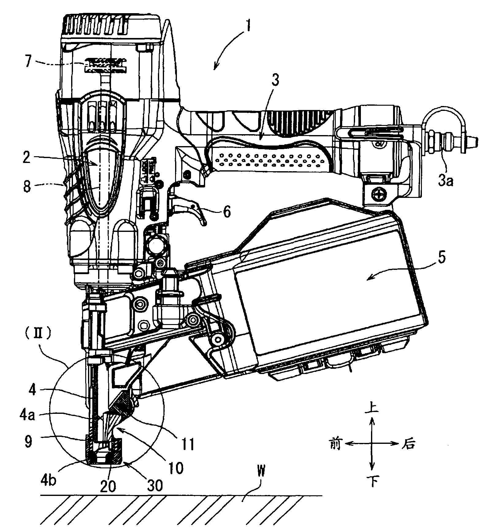
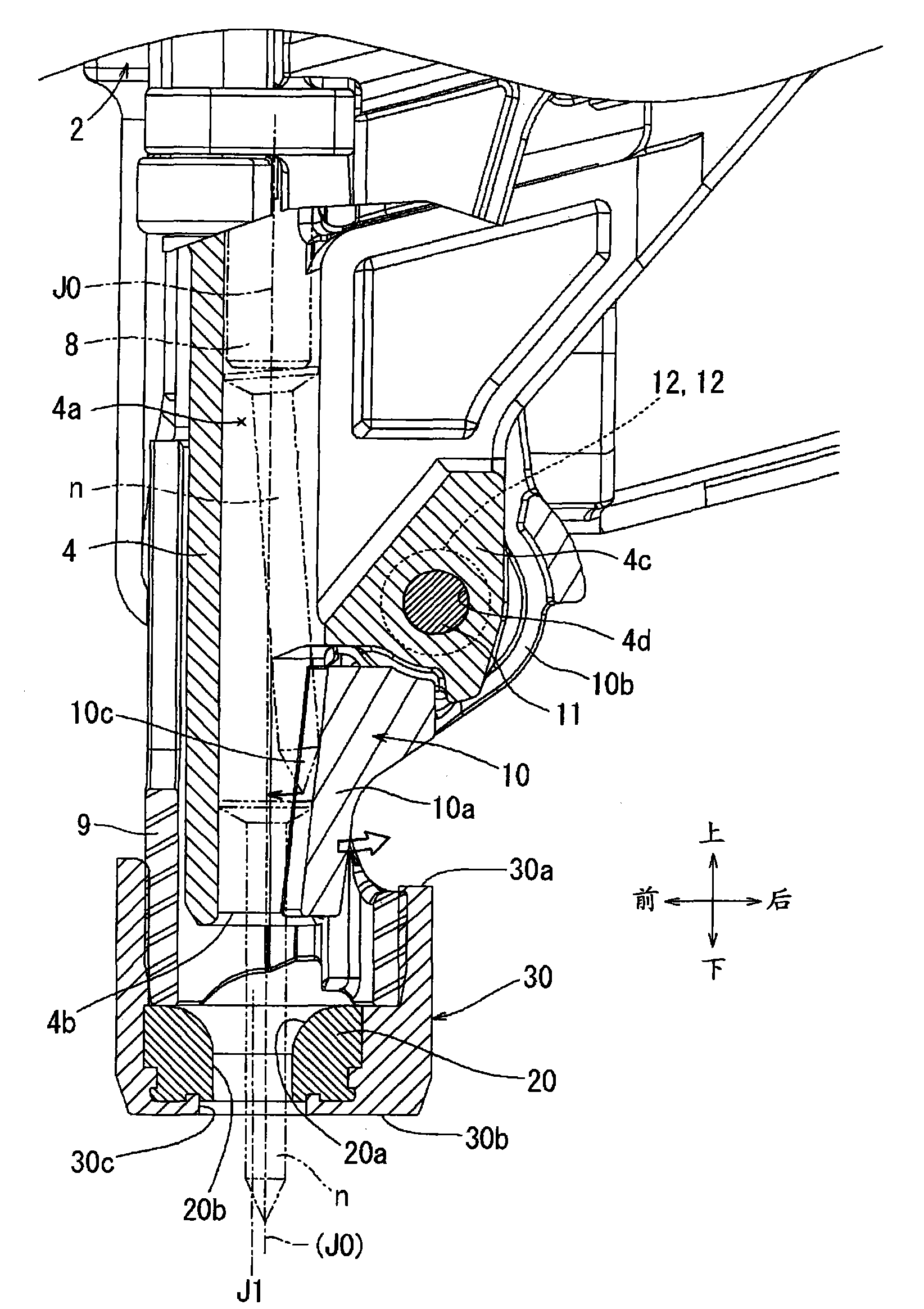
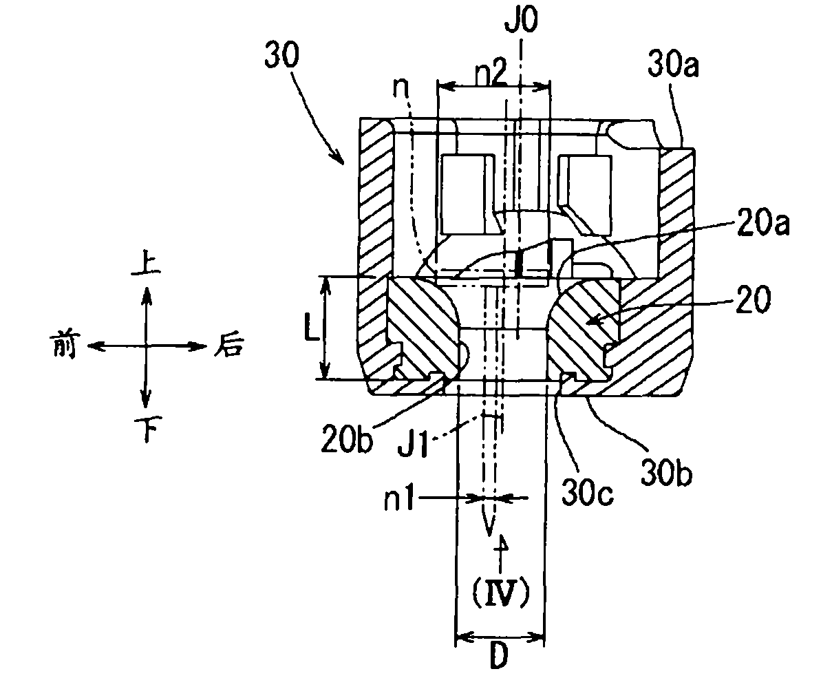
[0026] Next, refer to Figure 1 to Figure 7 Embodiments of the present invention will be described. figure 1 The whole of the driving tool 1 according to this embodiment is shown. The driving tool 1 of this embodiment is characterized by having a first restricting member for restricting the inclination of the driver n (inclination with respect to the moving direction of the driver 8 ) near the injection port to drive the driver n straightly. 10 and the second restricting member 20, other basic configurations of the driving tool do not need to be changed in particular, and thus detailed description thereof will be omitted. In addition, in this specification, regarding the up-down direction of a component or a structure, the driving direction of the driver n ( figure 1 The lower side) is the lower side, and the opposite direction is the upper side.

[0027] This driving tool 1 is a nailing machine driven by compressed air, and has: a body part 2 with a built-in piston 7; T...


PUM


Abstract

The invention relates to a punching tool. A conventional punching tool such as a box nailing machine which is rotatingly provided with a limiting part adjacent to a shooting outlet for limiting the position or inclination of a punched article is capable of punching a thin nail with a relatively small head part from the center of the shooting outlet in a straight way. However, the conventional punching tool which is limiting the rotation direction of the limiting part is unable to fully perform position or inclination limitation. Therefore, defective punching is especially to be decreased. The invention aims to reduce defective punching by more reliably limiting the position or inclination of punched articles. Specifically, the aim is achieved through the following ways of limiting the inclination of punched articles (n) in the front-back direction through a first limiting part (10) rotatingly supported by an actuator guide part (4); equipping a circular-ring shaped second limiting part (20) on an orifice adapter (30) equipped on a contact rod (9); and limiting the position or inclination of the punched articles (n) circumferentially through the second limiting part (20).

Description

technical field [0001] The invention relates to a hand-held tool used by a user, such as a nailing machine driven by compressed air and other driving tools. Background technique [0002] For example, a compressed air-driven driving tool has: a body part in which a piston that is reciprocated by compressed air is built; a driving guide that is protruded from the lower part of the body part It has a driving passage for the driver installed on the piston to drive through; a handle part extending sideways from the side of the main body part; a plurality of driving parts can be supplied to the driving passage one by one. The staple magazine for incoming pieces. [0003] When a switch lever in the form of a trigger provided near the base of the handle is pulled with a finger, compressed air is supplied to the cylinder upper chamber of the body to move the piston downward. When the piston is moved downward by the thrust of the compressed air, the driving part moves downward in th...

Claims


Application Information

Patent Timeline
Patent Type & Authority Patents(China)
IPC IPC(8): B25C1/04B25C3/00
Inventor 小田次郎岩上润一森冈康浩纸元顺平
Owner MAKITA CORP
Why Eureka
Try Eureka