Boundary Scanning chain self-testing method

A technology of boundary scan and boundary scan unit, which is applied in the direction of electronic circuit testing and detection of faulty computer hardware, etc. It can solve the problems of incomplete testing and low security, and achieve the effect of complete testing content and guaranteed testing safety

Inactive Publication Date: 2008-02-20
HUAWEI TECH CO LTD
View PDF4 Cites 0 Cited by
  • Summary
  • Abstract
  • Description
  • Claims
  • Application Information

AI Technical Summary

Problems solved by technology

[0008] The invention provides a boundary scan chain self-test method to solve the shortcomings of incomplete testing and low security in the prior art

Method used


Image

  • Boundary Scanning chain self-testing method
  • Boundary Scanning chain self-testing method
  • Boundary Scanning chain self-testing method

Examples


Embodiment Construction

[0037] The present invention will be further described below in conjunction with the accompanying drawings.

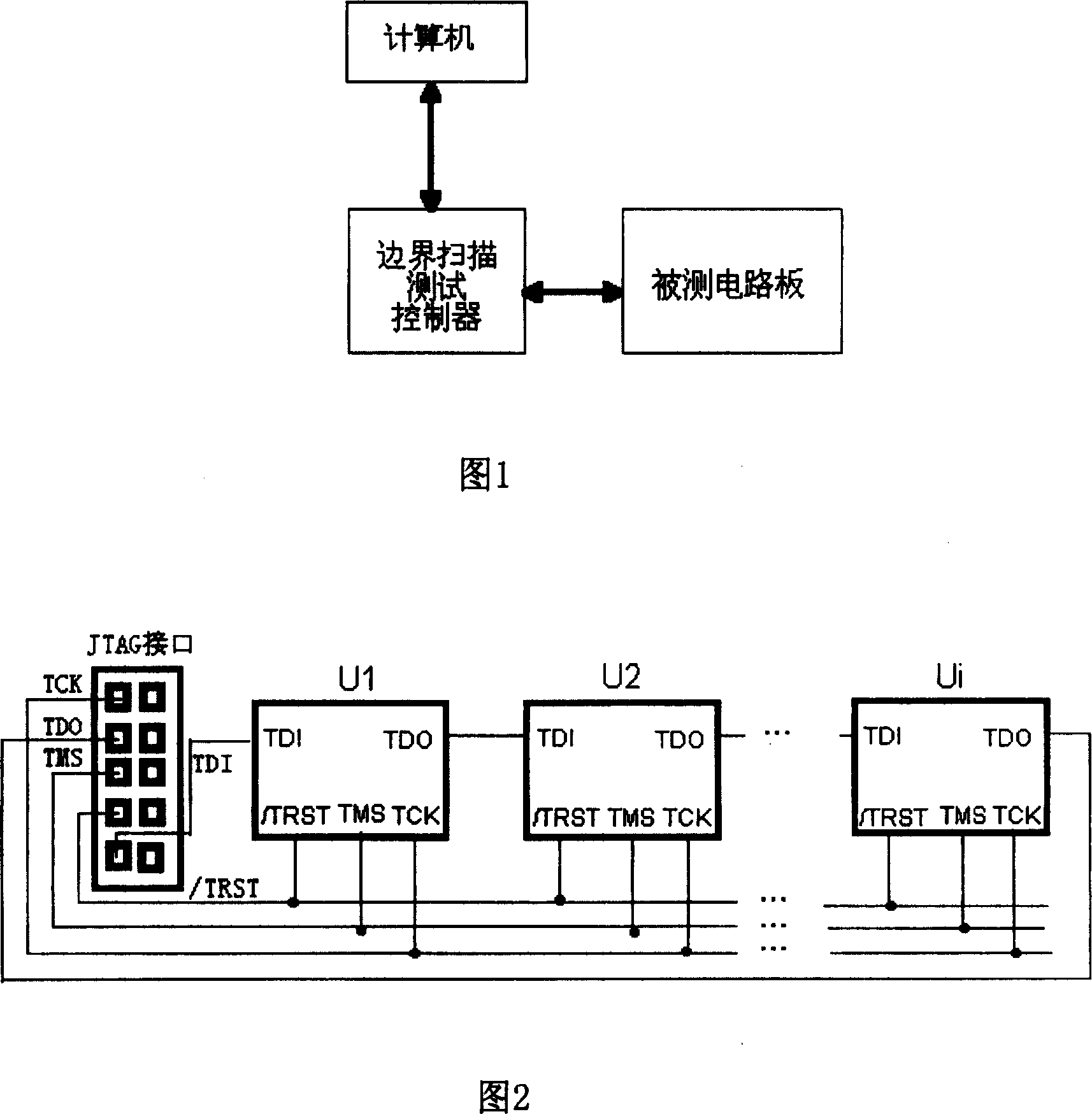
[0038] Fig. 7 is a flowchart of an embodiment of the method of the present invention. According to Figure 7, first determine the boundary scan chain to be tested in step 1, that is, connect the TDO line and TDI line of the boundary scan device to be tested on the circuit board in series, and connect the TMS, TCK and / TRST lines in parallel. At the same time, connect the above connection to the JTAG interface as well. Then proceed to step 2, according to the number of boundary scan devices on the boundary scan chain, and the bit length of each register to be tested in each boundary scan device and the number of boundary scan cells, determine the content that the boundary scan chain needs to test and its Corresponding length digits. The test content described here comprises register test and boundary-scan unit test; For register test, described length digit is the sum ...


PUM


Abstract

The present invention discloses a boundary scanning chain self-testing method. Firstly, defining content of boundary scanning chain which is required to be tested and length bit number correspondent to said content; according to said content adopting safe data whose length bit number is greater than that of the content required to be tested, making the safe data be followed after the data of the content required to be tested to make them be formed into tested sequence together, then making said tested sequence undergo the process of serial displacement operation, moving out the data in the tested content from scanning chain, and remaining safe data in the tested register or boundary scanning unit, finally, according to the data moved out from scanning chain judging that said scanning chain is in fault or not, remaining the content of safe data in the tested register or bondary scanning unit so as to ensure the testing safety.

Description

technical field [0001] The invention relates to a testing method for an integrated circuit, in particular to a testing method for a boundary scan (BS: BoundaryScan) integrated circuit. Background technique [0002] Currently, a boundary scan system for testing integrated circuits generally consists of the following three parts: a computer, a boundary scan test controller, and a circuit board under test, as shown in FIG. 1 . On the circuit board under test, the test data output (TDO: Test Data Output) line and the test data input (TDI: Test Data Input) line of the boundary scan device are connected in series, and the test mode input line (TMS: TestMode Select input), The test clock input line (TCK: Test Clock input) and the test logic reset line ( / TRST: Test Logic Reset) are connected in parallel, and the JTAG (Join Test Action Group) interface is the connection interface between the boundary scan test controller and the circuit board under test. Refer to In Fig. 2, U1, U2, ...

Claims


Application Information

Patent Timeline
Patent Type & Authority Patents(China)
IPC IPC(8): G06F11/22G01R31/28
Inventor 李颖悟徐光晓
Owner HUAWEI TECH CO LTD
Why Eureka
Try Eureka