
Polarized light phase compensating element and optical recording broadcaster with the same element

A phase compensation, optical recording technology, applied in optical recording heads, optical recording/reproducing, data recording, etc., can solve problems such as the inability to ensure the interchangeability of HD and DVD discs

Inactive Publication Date: 2008-02-27
LEJIN GUANGDIAN ELECTRONIC CO LTD SHANGHAI
View PDF3 Cites 0 Cited by
  • Summary
  • Abstract
  • Description
  • Claims
  • Application Information

AI Technical Summary

Problems solved by technology

Based on this, the optical record player using the above-mentioned phase compensation element cannot ensure the compatibility of HD and DVD discs.

Method used


Image

  • Polarized light phase compensating element and optical recording broadcaster with the same element
  • Polarized light phase compensating element and optical recording broadcaster with the same element
  • Polarized light phase compensating element and optical recording broadcaster with the same element

Examples


Embodiment Construction

[0073] Next, the embodiments according to the present invention will be described according to the accompanying drawings.

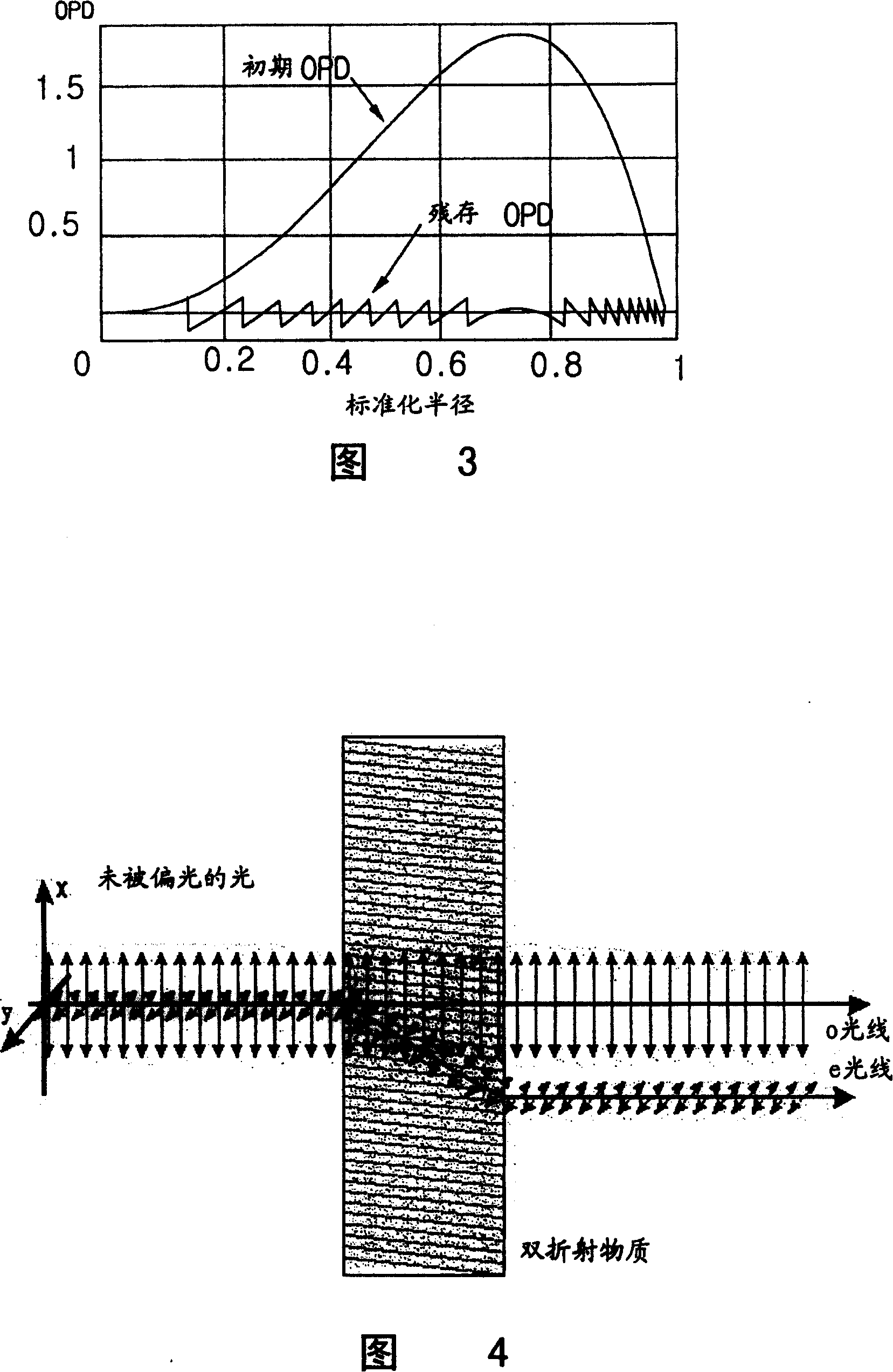
[0074] The present invention uses a plurality of birefringent media and a homogeneous media to form a polarized phase compensation element (PPC), which compensates spherical aberration generated by thickness differences of optical recording media. First, referring to FIG. 4 , observe the beam transmission characteristics of polarized light in a birefringent medium. Fig. 4 is a diagram showing the path of the transmitted beam when it is incident on a beam polarized in a general birefringent medium.

[0075] When a polarized beam is incident on a birefringent medium, the path of the transmitted beam will be different according to the polarization direction of the incident beam. That is, as shown in FIG. 4 , for a birefringent medium, a beam polarized in the X-axis direction does not change the direction of the beam when passing through the birefringent med...


PUM

PropertyMeasurementUnit
wavelengthaaaaaaaaaa
thicknessaaaaaaaaaa
thicknessaaaaaaaaaa

Abstract

The optical recording device with polarized light phase compensator combines one homogeneous medium and several birefringent media, and includes polarized light phase compensator for regulating transmitted light path according to the incident light wavelength and the polarized light direction and objective for focusing the light beam from the polarized light phase compensator onto the light record medium suitable for different light wavelength. In addition, for record medium with different, high, medium and low, density, homogeneous medium, the first birefringent medium and the second birefringent medium in proper light refraction indexes are selected.

Description

technical field [0001] The present invention relates to optical record players. More specifically, it relates to an optical record player capable of recording and reproducing data interchangeably on heterogeneous discs of different types (standards) of optical recording media. Background technique [0002] Recently, with the development of high-density and high-capacity optical recording media, in order to reduce the size of the light beam for recording and playback, increase the numerical aperture (NA: Numerical Aperture) of the objective lens, and shorten the length of the light source (for example: laser) wavelength for the purpose of developing the structure of the optical record player. Here, the high-density recording medium is exemplified by an HD disc, the medium-density medium is exemplified by a DVD disc, and the low-density recording medium is exemplified by a CD disc for illustration. [0003] For example, the light source wavelength of a low-density recording ...

Claims


Application Information

Patent Timeline
Patent Type & Authority Patents(China)
IPC IPC(8): G11B7/00G11B7/12G11B7/125G11B7/135G11B7/1275G11B7/1392
Inventor 李京彦
Owner LEJIN GUANGDIAN ELECTRONIC CO LTD SHANGHAI
Learn More