Optical pickup device

A technology of beam and optical axis, applied in the direction of beam guiding device, optical detector, instrument, etc., can solve the problems of inability to obtain focus state, FES curve offset, and inability to obtain FES curve, etc.

Inactive Publication Date: 2006-07-12
SHARP KK
View PDF5 Cites 0 Cited by
  • Summary
  • Abstract
  • Description
  • Claims
  • Application Information

AI Technical Summary

Problems solved by technology

[0031] Therefore, the light beam is sensed by the auxiliary photosensitive area for focusing, so that the FES curve is shifted, as shown in Figure 17, and a good FES curve cannot be obtained
[0032] Also, for example, when reproducing a two-layer optical disc whose interlayer distance is d2, in the above-mentioned aberration detection device, the FES shift of Δd2 occurs in the FES, and a correct in-focus state cannot be obtained.

Method used


Image

  • Optical pickup device
  • Optical pickup device
  • Optical pickup device

Examples


Embodiment approach 1

[0062] An embodiment of the present invention is described as follows according to the accompanying drawings.

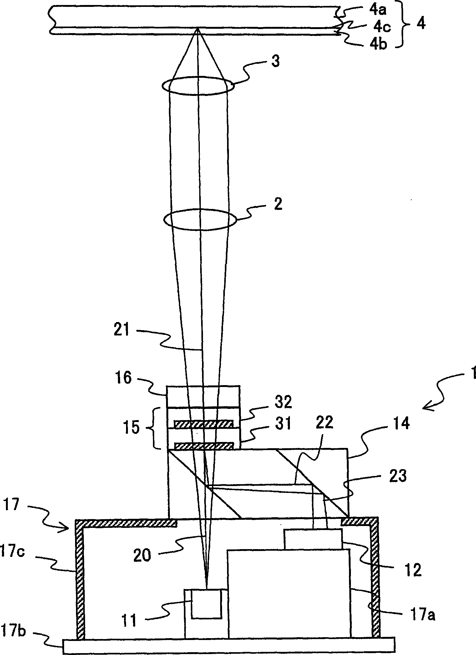
[0063] Such as figure 2 As shown, the optical pickup device of the present embodiment has an optical integration unit 1 , a collimator lens 2 and an objective lens (light condensing unit) 3 . The light emitted from the optical integration unit 1 is focused onto the optical disc 4 through the collimator lens 2 and the objective lens 3 , and is reflected on the optical disc 4 . Then, the reflected light is focused on the photosensitive element 12 (described later) in the optical integration unit 1 through the objective lens 3 and the collimating lens 2 .

[0064] In the optical pick-up device of present embodiment, the laser light source of the short-wavelength light beam that irradiates wavelength 405nm left and right sides is used as the light source that optical integration unit 1 prepares, and the high NA objective lens that numerical aperture NA is about 0.85 is...

Embodiment approach 2

[0146] Another embodiment of the present invention is described as follows with reference to the accompanying drawings. Components having the same functions as those in Embodiment 1 are denoted by the same reference numerals, and description thereof will be omitted.

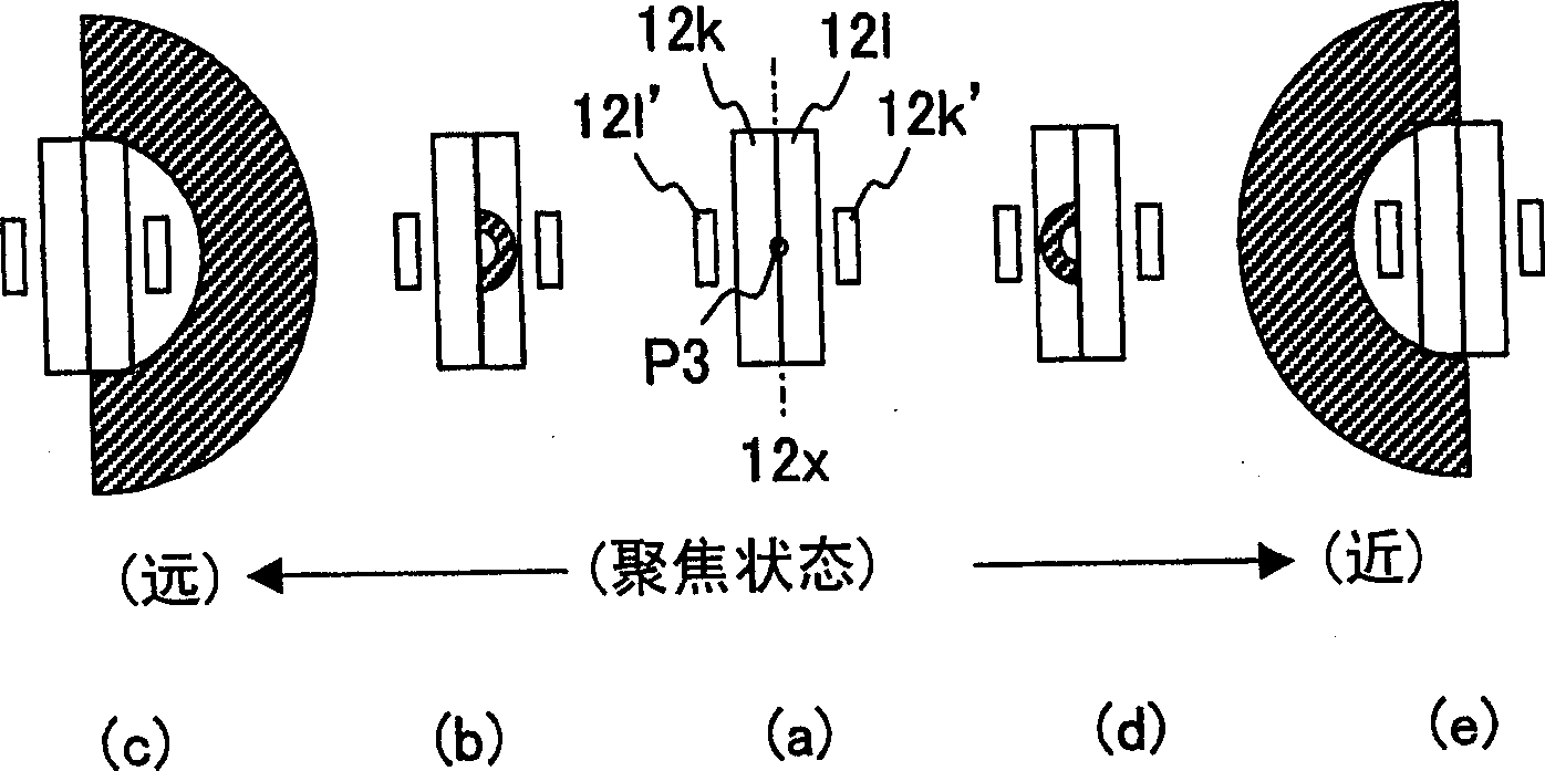
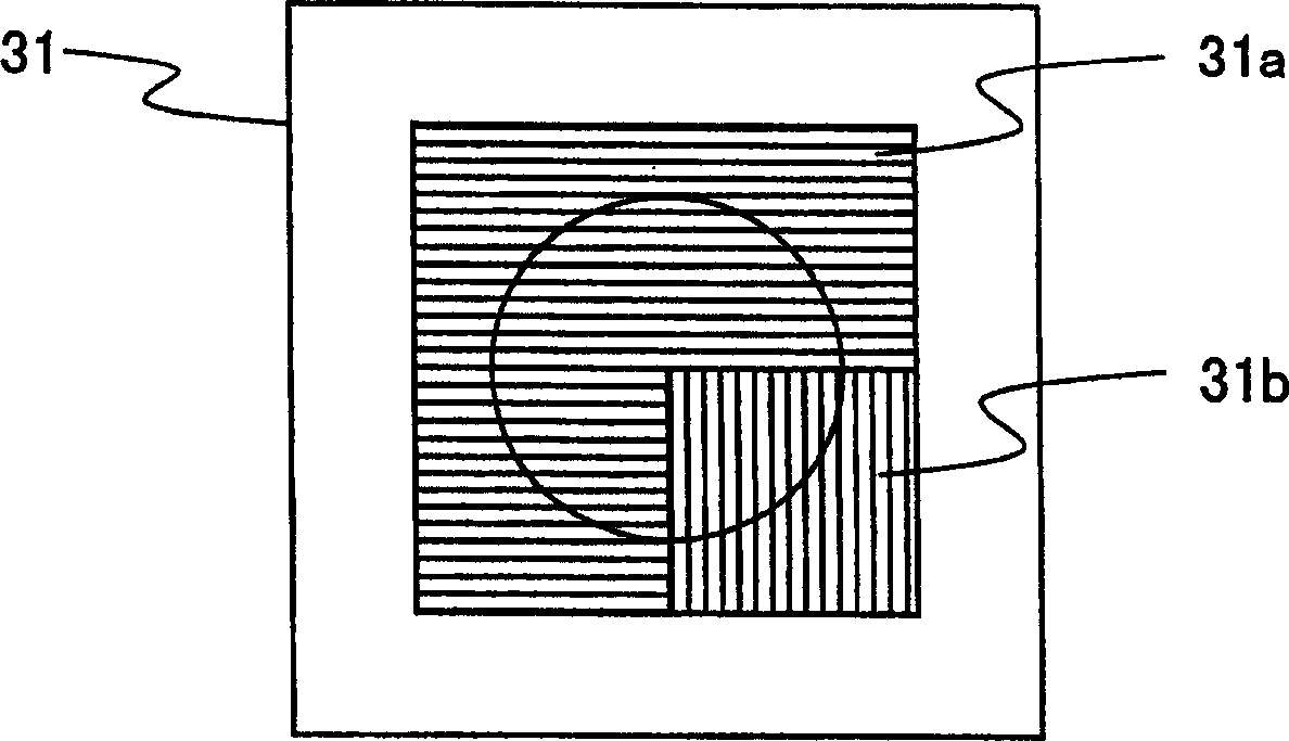
[0147] In this embodiment, among the light beam P1 diffracted by the region 32a of the second polarization hologram element 32, in other words, among the light beams irradiated on the second polarization hologram element 32, the main photosensitive region 12i, which irradiates the light beam P1 including the optical axis of the light beam, The relationship between the shape of 12j and the auxiliary photosensitive regions 12i', 12j' and the shape of the main photosensitive regions 12k, 12l and the auxiliary photosensitive regions 12k', 12l' on which the light beam P3 is irradiated. Specifically, this embodiment describes that the length of the first main photosensitive regions 12i, 12j that are sensitive to the li...

Embodiment approach 3

[0165] Still another embodiment will be described below with reference to the drawings. Components having the same functions as those described in Embodiment 1 are denoted by the same reference numerals, and description thereof will be omitted.

[0166] In this embodiment, all the main photosensitive regions 12i, 12j, 12k, 12l, and 12m irradiated with light beams P1, P2, and P3 diffracted by the regions 32a, 32b, and 32c of the second polarization hologram element 32 divided into three regions will be described. , 12n and auxiliary photosensitive regions 12i', 12j', 12k', 12l', 12m', 12n' to obtain an example of FES.

[0167] Next, in this embodiment, the second main photosensitive regions 12m and 12n and the second auxiliary photosensitive regions 12m' and 12n' that are irradiated with the light beam P2 will be described.

[0168] In the present embodiment, the focus error signal FES is detected by the double-knife method, but the FES is detected by light diffracted by the r...


PUM


Abstract

An optical pickup device includes: a separation section for separating a light beam into (i) a first light beam, which includes an optical axis of the light beam, and (ii) a second light beam, which surrounds a curved side of the first light beam; and a second light receiving section for receiving the light beam. The second light receiving section includes (I) main light receiving regions, which are provided with a division line therebetween so as to be adjacent to each other and (II) auxiliary light receiving regions, which receive a portion of the light beam which protrudes from each of the main light receiving regions. Each of the auxiliary light receiving regions is positioned in a direction orthogonal to a drawing direction of the division line so as to be adjacent to the main light receiving region. The auxiliary light receiving region is shorter than the main light receiving region in the drawing direction of the division line.

Description

field of invention [0001] The present invention relates to an optical pickup device mounted in an optical disc device for optically recording or reproducing information on an information recording medium such as an optical disc. optical pickup device. Background technique [0002] In recent years, optical discs have been able to record a large amount of information signals at a high density, and their utilization in many fields such as audio, video, and computers has accelerated. Recently, in order to increase the recording capacity, an optical recording medium adapted to a case where a recording medium having a plurality of recording layers is provided, or a case where laser light has a shorter wavelength or the numerical aperture of an objective lens is enlarged has been proposed. [0003] In the case of using an optical recording medium with a small distance between recording and reproducing surfaces in the recording medium having a plurality of recording layers as descr...

Claims


Application Information

Patent Timeline
Patent Type & Authority Applications(China)
IPC IPC(8): G11B7/12G11B7/13G11B7/135
CPCG11B7/1381G11B7/13927G11B2007/0013G11B7/131G11B7/0948G11B7/1395G11B7/1353
Inventor 堀山真
Owner SHARP KK
Why Eureka
Try Eureka