
Optical pickup device

A technology for optical pick-up and calibration devices, applied in optics, beam guiding devices, optical elements, etc., can solve the problems of increasing the size of the optical pick-up device, increasing the number of components of the optical pick-up device, and complicating the optical pick-up device

Inactive Publication Date: 2007-02-28
FUNAI ELECTRIC CO LTD
View PDF1 Cites 1 Cited by
  • Summary
  • Abstract
  • Description
  • Claims
  • Application Information

AI Technical Summary

Problems solved by technology

This disadvantageously increases the number of components of the optical pickup device, increases the size of the optical pickup device itself, and makes the optical pickup device complicated.

Method used


Image

  • Optical pickup device
  • Optical pickup device
  • Optical pickup device

Examples


Embodiment Construction

[0024] Embodiments of the present invention will be described below with reference to the drawings. It should be understood that the structures described below are only examples of how to implement the present invention, and therefore do not mean any limitation to the present invention.

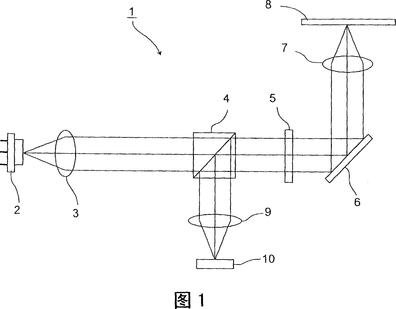
[0025] FIG. 1 is a schematic diagram of an optical system of an optical pickup device implementing the present invention. In Fig. 1, in order to read information on the signal recording surface of optical recording medium 8 and write information to the signal recording surface of optical recording medium 8, optical pick-up device 1 is to the optical recording medium such as CD, DVD or Blu-ray DVD or the like 8 and receives light reflected from the optical recording medium 8 . The optical pickup device 1 is provided with, for example, a laser light source 2 , a collimator lens 3 , a beam splitter 4 , a quarter-wave plate 5 , a deformable mirror 6 , an objective lens 7 , a condenser lens 9 , a...


PUM


Abstract

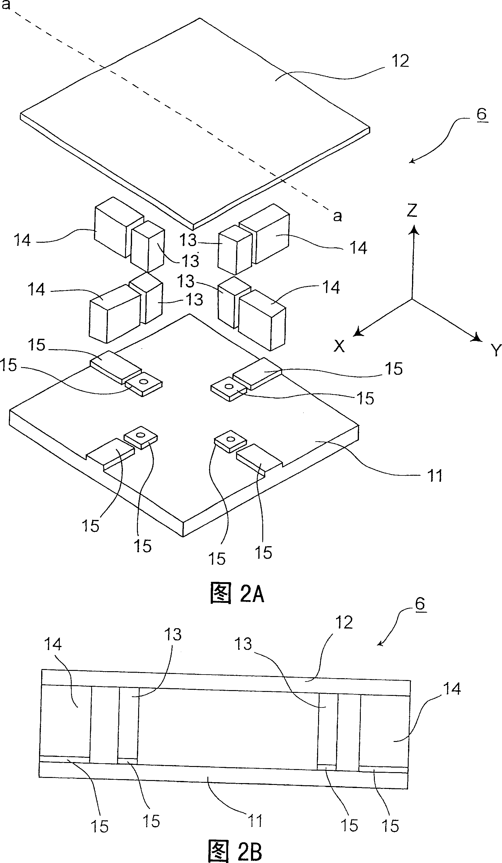
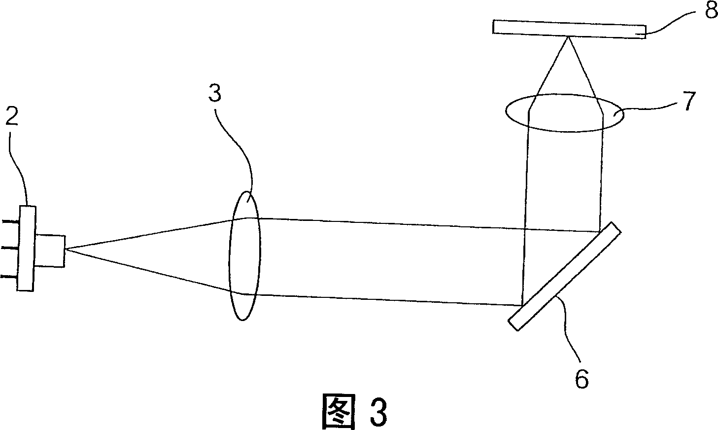
An optical pickup device has a variable-shape mirror that reflects a light beam emitted from a light source and that, by use of piezoelectric elements sandwiched between a support substrate and a mirror portion arranged to face the support substrate, corrects for wavefront aberrations in the light beam by deforming a mirror surface of the mirror portion, and converging means for directing, while condensing, the light beam reflected from the variableshape mirror to a recording surface of an optical recording medium. Let a direction perpendicular to the travel direction of the light beam emitted from the light source be the X direction on the mirror surface and let the direction perpendicular to the X direction be the Y direction on the mirror surface, the mirror surface is inclined about the X direction such that the mirror surface forms a predetermined angle relative to the travel direction of the light beam emitted from the light source. The piezoelectric elements are arranged symmetrically about the center axis of the mirror surface, with two of them arranged in the X direction and another two in the Y direction. The piezoelectric elements are arranged on the support substrate such that, when all of them are driven with equal voltages, the curvature of the mirror surface in the X direction relative to the curvature of the mirror surface in the Y direction fulfills a predetermined curvature ratio.

Description

technical field [0001] The present invention relates to an optical pickup device for reading or recording information on an optical recording medium such as DVD or CD-ROM, and more particularly to an optical pickup device capable of correcting wavefront aberration by using a deformable mirror . Background technique [0002] As conventional optical recording media, music CDs (Compact Discs) or video DVDs (Digital Versatile Discs) have been in practical use for a long time, and have developed into high-capacity, high-quality DVDs, Blu-ray DVDs, etc. in recent years. As a drive device for accessing optical recording media such as CDs, DVDs, and Blu-ray DVDs, optical disc devices have been widely used. An optical disc device records information on and erases information from an optical recording medium by irradiating laser light on the recording surface of the optical recording medium, and retrieves information from the optical recording medium based on light reflected from the...

Claims


Application Information

Patent Timeline
Patent Type & Authority Applications(China)
IPC IPC(8): G11B7/12G11B7/135G02B26/06
CPCG11B7/13925G11B7/1362G02B26/0858
Inventor 长岛贤治藤井仁田中史记杉山进石井明田中克彦久濑亘
Owner FUNAI ELECTRIC CO LTD
Learn More