Deformable mirror device, deformable mirror plate
A technology of deformable mirrors and devices, applied in the direction of instruments, mirrors, optical components, etc., to achieve the effect of preventing cracks
- Summary
- Abstract
- Description
- Claims
- Application Information
AI Technical Summary
Problems solved by technology
Method used
Image
Examples
no. 1 approach
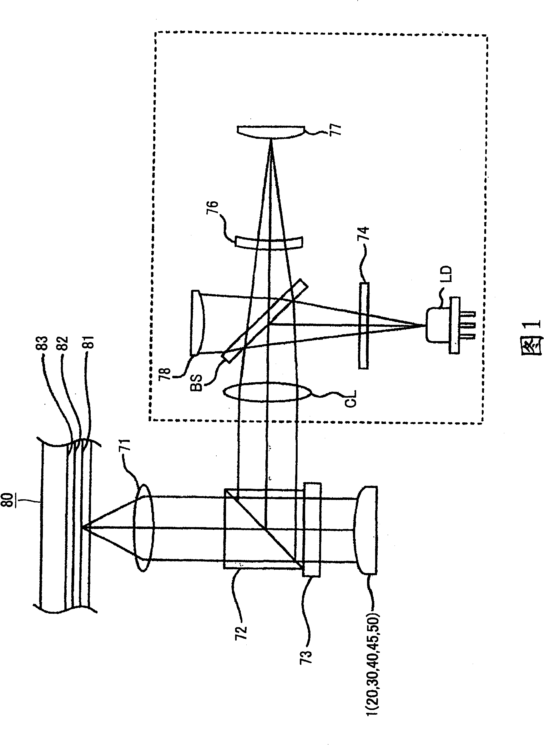
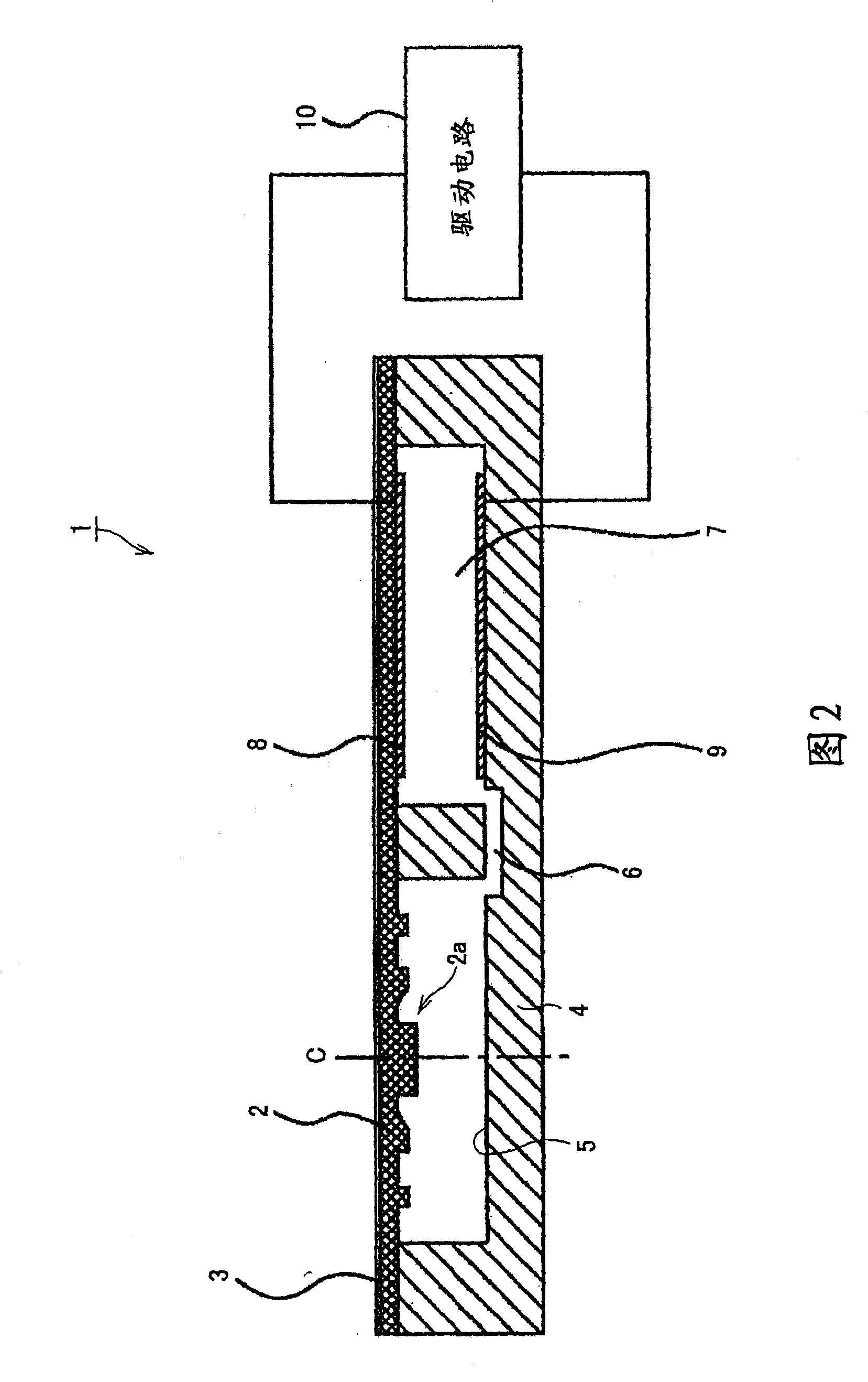
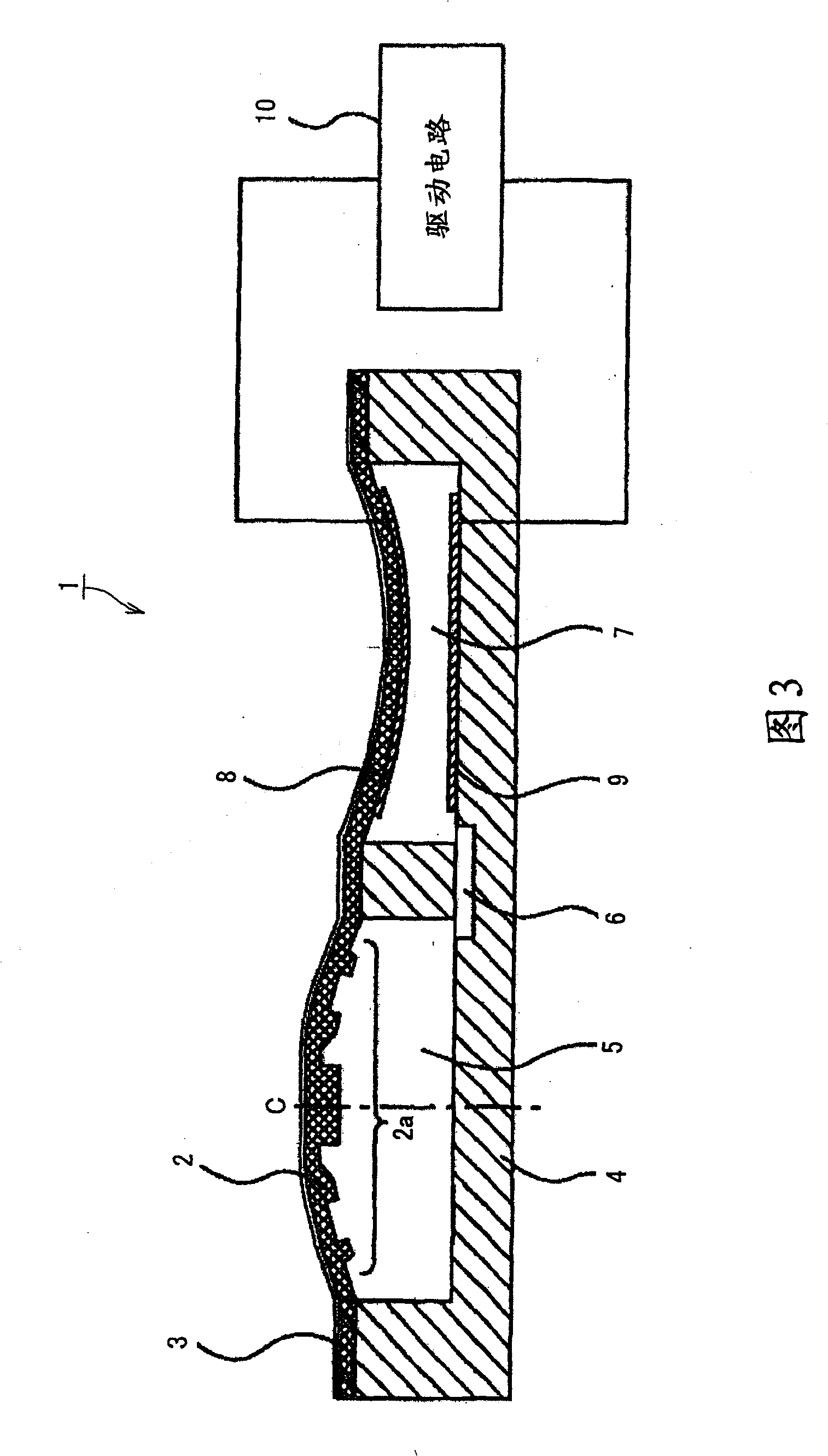
[0069] First, a first embodiment of the deformable mirror device 1 according to the present invention will be described below by referring to FIG. 2 . The deformable mirror device 1 deforms a mirror surface by using a flexible member that assumes a different part state in a deformation mode when a part with a different cross-sectional profile is formed and an intensity distribution pattern is given.
[0070] As shown in FIG. 2 , a deformable mirror device 1 according to the present invention includes at least a flexible member 2 , a reflective film 3 , a substrate 4 , an upper electrode 8 and a lower electrode 9 . The substrate 4 of the mirror device 1 is provided with two circular grooves for creating a first space 5 and a second space 7, the two grooves being arranged side by side. The first space 5 and the second space 7 defined by the two grooves are connected to each other by a flow channel 6 .
[0071] The flexible member 2 is bonded to the substrate 4 so as to cover th...
no. 2 approach
[0103] Now, a second embodiment of the present invention will be described below by referring to FIG. 6 . The deformable mirror device 20 of the second embodiment is different from the first embodiment in that the first embodiment is adapted to generate a driving force for deforming the mirror surface by the attractive force between the upper electrode 8 and the lower electrode 9, while the second embodiment The embodiment is suitable for generating a driving force for deforming a mirror surface by deformation of the piezoelectric element 21 .
[0104] In FIG. 6 , the same components as those of the first embodiment are denoted by the same reference symbols, respectively, and will not be further described.
[0105] In the deformable mirror device 20, the flexible member 2 is bonded to the substrate 4 so as to cover only the first space 5, as shown in FIG. 6 . On the second space 7 side, an elastic conductive plate 22 is bonded to the substrate 4 so as to cover only the second...
no. 3 approach
[0116] Now, a third embodiment of the present invention will be described below by referring to FIG. 7 . The deformable mirror device 30 of the third embodiment is adapted to deform the mirror surface by directly pushing or pulling the surface of the flexible member 2 on which the intensity distribution pattern 2a is formed by means of a voice coil motor.
[0117] As shown in FIG. 7 , the mirror device 30 has a single circular space 37 in the substrate 4 . The flexible member 2 is bonded to the substrate 4 in such a way that the central axis C of the circular space 37 is aligned with the center of the intensity distribution pattern 2a exhibiting a concentrically arranged circular shape. The voice coil motor 31 is fixed to the substrate 4 in the space 37 .
[0118] The voice coil motor 31 is rigidly fixed in place on the substrate 4 with the central axis of its cylindrical yoke 32 aligned with the central axis C of the space 37 . The cylindrical yoke 32 is provided with a fla...
PUM
| Property | Measurement | Unit |
|---|---|---|
| thickness | aaaaa | aaaaa |
| thickness | aaaaa | aaaaa |
| thickness | aaaaa | aaaaa |
Abstract
Description
Claims
Application Information
 - R&D
- Intellectual Property
- Life Sciences
- Materials
- Tech Scout
- Unparalleled Data Quality
- Higher Quality Content
- 60% Fewer Hallucinations
Browse by: Latest US Patents, China's latest patents, Technical Efficacy Thesaurus, Application Domain, Technology Topic, Popular Technical Reports.
© 2025 PatSnap. All rights reserved.Legal|Privacy policy|Modern Slavery Act Transparency Statement|Sitemap|About US| Contact US: help@patsnap.com


