Gas burner crown for kitchen hobs

A technology for gas stoves and hob, which is applied in the field of gas stove crowns and can solve problems such as restrictions and the like

Inactive Publication Date: 2008-06-04
SO M I PRESS SOC METALLI I
View PDF7 Cites 2 Cited by
  • Summary
  • Abstract
  • Description
  • Claims
  • Application Information

AI Technical Summary

Problems solved by technology

[0008] For the aforementioned reasons, the construction and position of the gas hob on the hob has so far been limited due to the design of the pan support
[0009] The disadvantage of this type of gas cooker is that the crown is designed for a specific configuration, in fact, in case for commercial or aesthetic reasons a modification of the design of the pan support is required, i.e. from cross-shaped spokes to X-shaped spokes, then The position of the stove body, the gas connection pipe and the faucet also need to be modified

Method used


Image

  • Gas burner crown for kitchen hobs
  • Gas burner crown for kitchen hobs
  • Gas burner crown for kitchen hobs

Examples


Embodiment Construction

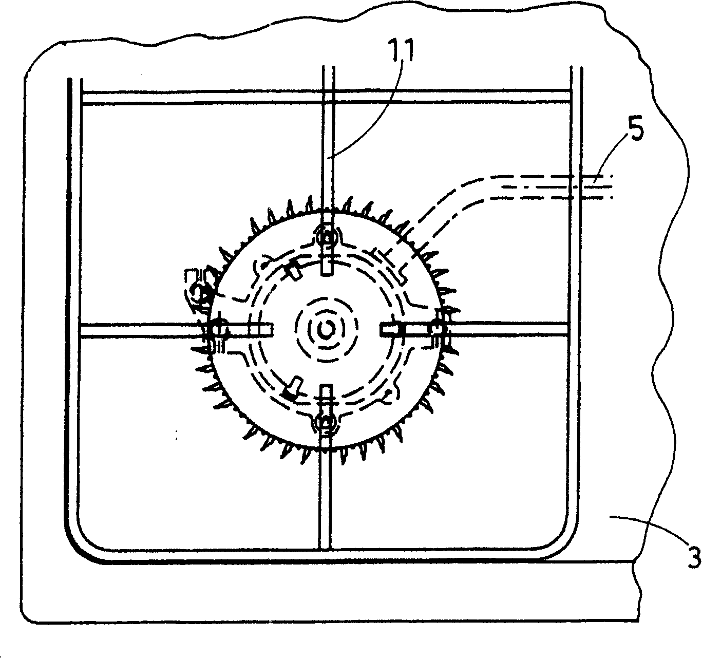
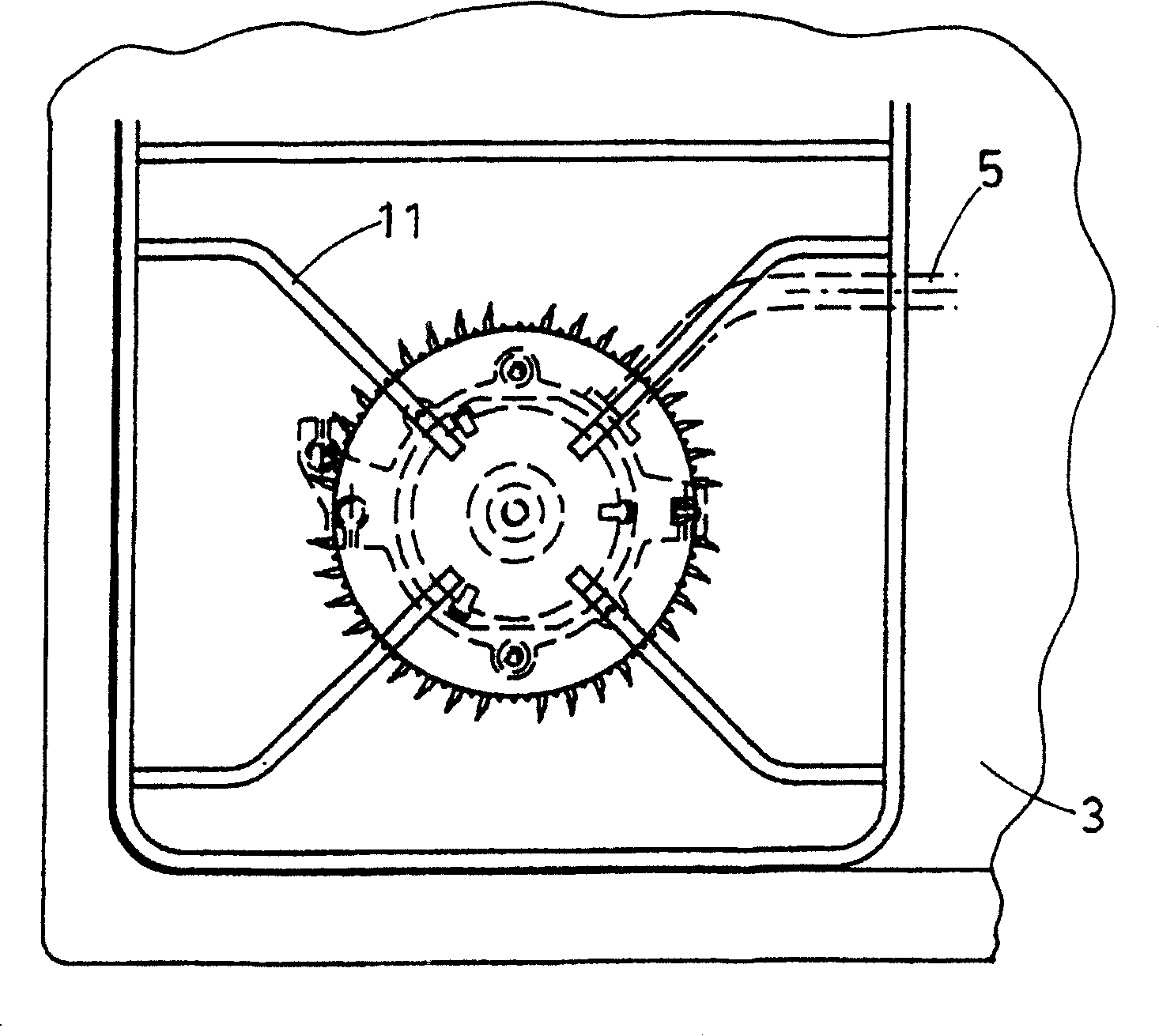
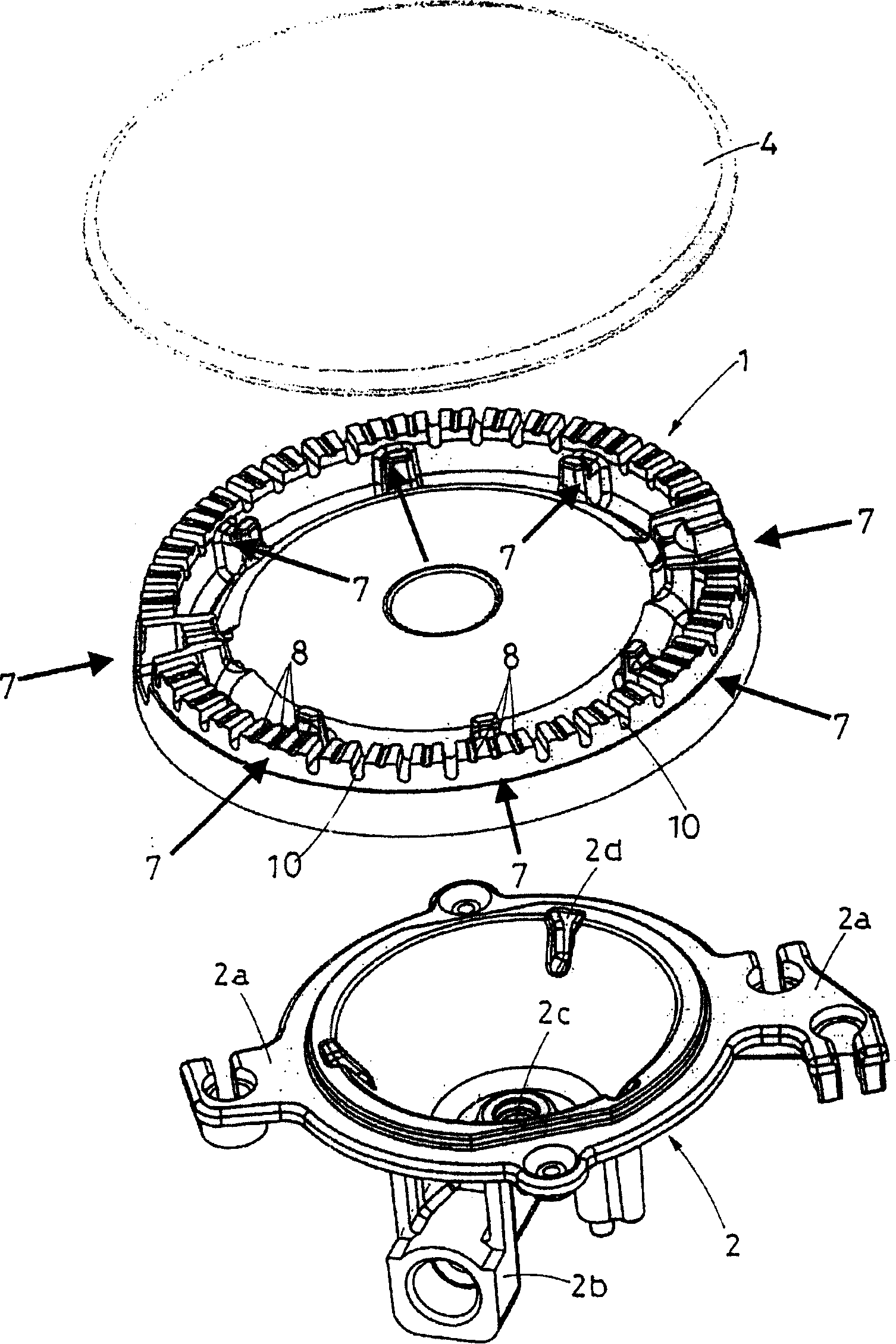
[0019] As shown in the aforementioned drawings cited, the furnace crown 1 of the present invention is designed for a traditional gas range, and its range body 2 has a peripheral bracket 2a for stably fixed under the hob 3, and a cover with a cover is placed on the peripheral bracket 4 for the furnace crown 1.

[0020] The stove body 2 has a radial nozzle 2 b extending outwards connected to the gas supply pipe 5 , and the nozzle is located below the stove frame 3 . The end of the nozzle 2b is a hole 2c at the bottom of the stove body 2, and internal grooves 2d are distributed at even intervals on the upper edge, which precisely accommodate the teeth located under the furnace crown 1, so as to prevent the furnace crown 1 from moving The kitchen range body 2 rotates freely.

[0021] The cover 4 is placed over the crown 1 which has a series of evenly spaced radial grooves which act as small gas burner nozzles from which small radial flames are produced.

[0022] The crown 1 of t...


PUM


Abstract

The present invention refers to a gas burner crown for kitchen hob, of the type with a radial series of notches, composed of shallower notches alternated with deeper notches, which act as small burner nozzles, from which small radial flames originate; the crown is characterised by the presence of eight regularly spaced angular sectors with shallower radial notches.

Description

technical field [0001] The present invention relates to a gas range crown for a kitchen hob, which allows the use of cross or X-shaped pan supports without having to rotate the gas range crown at an angle of 45 degrees. Background technique [0002] The model of the invention is based on a modified crown available on the market for kitchen hob gas stove crowns with pan supports. The gas stove is composed of a hollow cone with the top truncated. There are nozzles on the stove body connected to the gas supply pipe. A groove-shaped crown is placed on the edge of the stove body to support a ring-shaped cover, so that the gas flows into the stove. In the body, blow through the dense radial series of grooves on the upper edge of the furnace crown. [0003] Since there are teeth matching the corresponding grooves on the stove body below the stove crown, the stove crown matches the stove body so that the free rotation of the stove crown can be prevented. [0004] The gas supply pi...

Claims


Application Information

Patent Timeline
Patent Type & Authority Patents(China)
IPC IPC(8): F23D14/06F24C3/08F24C15/10
CPCF24C3/085F23D14/06
Inventor 彼罗·阿尔曼尼
Owner SO M I PRESS SOC METALLI I
Why Eureka
Try Eureka