Jet-flow oscillator

An oscillator and jet technology, applied in the direction of injection device, injection device, etc., can solve the problems of insufficient vibration and large energy loss, and achieve the effect of reliable use and improved energy utilization.

Inactive Publication Date: 2008-10-22
孙厚钧
View PDF12 Cites 1 Cited by
  • Summary
  • Abstract
  • Description
  • Claims
  • Application Information

AI Technical Summary

Problems solved by technology

However, due to the relatively flat shape and basic symmetry of the left and right feedback vortex chambers of this device, the vibration is not violent enough and the energy loss is large.

Method used


Image

  • Jet-flow oscillator
  • Jet-flow oscillator
  • Jet-flow oscillator

Examples


Embodiment Construction

[0027] The following examples are used to illustrate the present invention, but are not intended to limit the protection scope of the present invention.

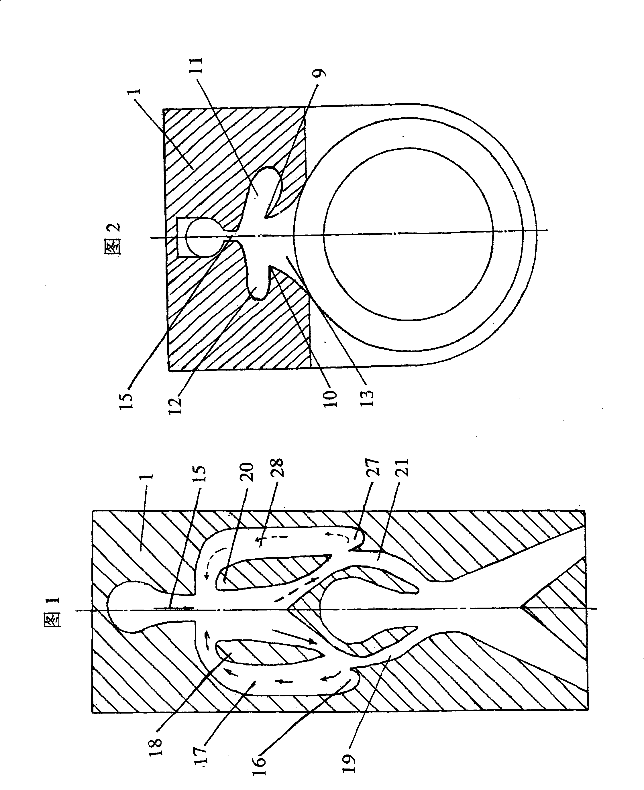
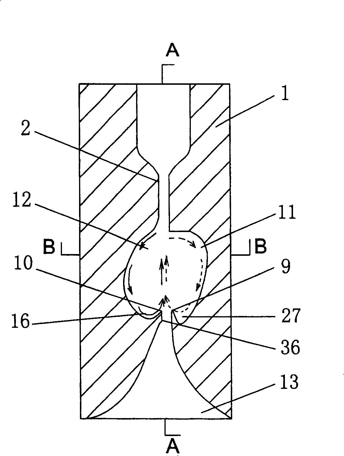
[0028] see image 3 , Figure 4 with Figure 5. The first embodiment of the jet oscillator of the present invention includes a main body 1, and a water inlet pipe 2, an oscillation chamber, and a gradually widening output port 13 are arranged in the main body 1, wherein the oscillation chamber includes a main channel and is located on the left side of the main channel. , the left feedback vortex chamber 12 and the right feedback vortex chamber 11 of the smooth transition surface shape on both sides of the right side, the left and right feedback vortex chambers form the left tip 10 and the right tip 9 at the connection with the gradually widening output port 13, Correspondingly, the left and right feedback vortex chambers respectively form a left reflection bucket 16 and a right reflection bucket 27 near the gradual widenin...


PUM


Abstract

The present invention relates to a jet flow oscillator. It mainly includes the following several portions: self-body, water inlet pipe, oscillation chamber, high-pressure nozzle and output hole. Said invention also provides the concrete structure of above-mentioned every portion and connection mode of all the above-mentioned portions. Besides, said invention also provides the working principle of said jet flow oscillator and its concrete operation method.

Description

technical field [0001] The invention relates to an oscillator, especially a jet oscillator used in fluid. Background technique [0002] Invented and authorized by the inventor, a utility model patent named "Jet Oscillating Liquid Mixing Inflator" and patent No. ZL98218398.4 discloses a jet oscillator for fluid, as shown in Figure 1. Its structure includes The main body 1 is provided with a water inlet pipe, an oscillating chamber, a left output flow channel 19 and a right output flow channel 21 which communicate with each other in the main body 1, wherein the oscillating chamber is divided into a central main flow channel and a central main channel by a left partition 18 and a right partition 20. The left feedback channel 17 and the right feedback channel 28 located on the left and right sides respectively form a left reflection bucket 16 and a right reflection bucket 27 on the left and right feedback channels. High pressure nozzle. Oscillation principle is: the jet ejecte...

Claims


Application Information

Patent Timeline
Patent Type & Authority Patents(China)
IPC IPC(8): B05B1/08
Inventor 孙厚钧
Owner 孙厚钧
Why Eureka
Try Eureka