
Friction control device for railway vehicle

A technology for railway vehicles and control devices, which is applied to railway car body parts, measuring devices, and mechanical devices, etc., can solve the problems of inability to change the coating amount of friction modifier and difficulty in friction state.

Inactive Publication Date: 2008-11-19
NIPPON STEEL CORP
View PDF8 Cites 0 Cited by
  • Summary
  • Abstract
  • Description
  • Claims
  • Application Information

AI Technical Summary

Problems solved by technology

However, in this case, in these inventions, it is not possible to change the application amount of the friction modifier according to the fluctuating frictional force.
[0011] As mentioned above, although it is currently considered to be technically difficult to quantitatively and accurately measure the friction state between the wheel and the curved guide rail during driving

Method used


Image

  • Friction control device for railway vehicle
  • Friction control device for railway vehicle
  • Friction control device for railway vehicle

Examples


Embodiment approach 1

[0085] The present invention will be described more specifically below with reference to examples.

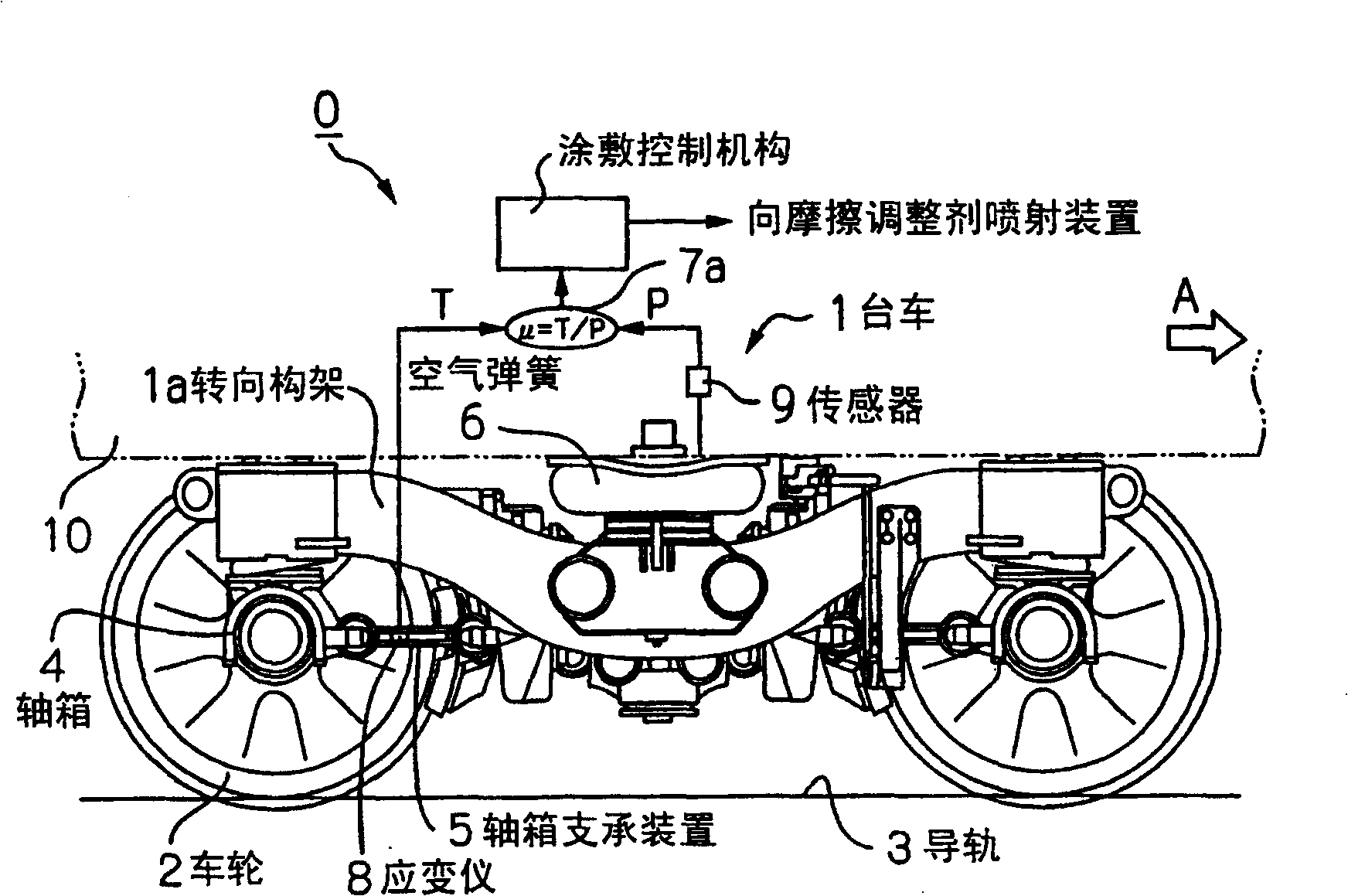
[0086] make it equipped with such figure 1 The railway vehicle of the railway vehicle trolley 1 of the friction control device 0 of the present invention shown travels on a curved guide rail 3 with a radius of 200 m or 130 m, respectively. Furthermore, based on the cases where the friction modifier between the wheels 2 and the curved guide rail 3 is controlled by spraying the friction modifier on the curved guide rail 3 and the case where the friction control is not performed, the effects on the wheels 2 located on the rear side in the direction of travel are analyzed. The relationship between the front and rear force T and the up and down force P and the friction coefficient μ.

[0087] In addition, the front-rear force T is obtained by attaching the strain gauge 8 to the axle box supporting devices 5, 5 of the left and right wheels 2, 2 on the rear side of the trolley 1 in t...

Embodiment 2

[0094] In general, it is known that when the coefficient of friction between the wheel and the curved guide becomes high, noise, vibration, and wear of the curved guide increase. Conventionally, the evaluation of the frictional state between the wheel and the curved guide rail is generally evaluated using the ratio (Q / P) of the wheel weight Q of the front axle located on the front side in the traveling direction to the lateral pressure P. That is, if the ratio (Q / P) exceeds 0.4, the noise, vibration, and wear will all become excessive. Therefore, in the present invention, the relationship between the above-mentioned friction coefficient μ and the ratio (Q / P) used as a control factor is analyzed. relationship between.

[0095] Figure 7 It is a graph showing the relationship between the ratio (Q / P) of the wheel load Q to the lateral pressure P of the front axle located on the front side in the traveling direction and the coefficient of friction (T / P) specified in the present i...


PUM


Abstract

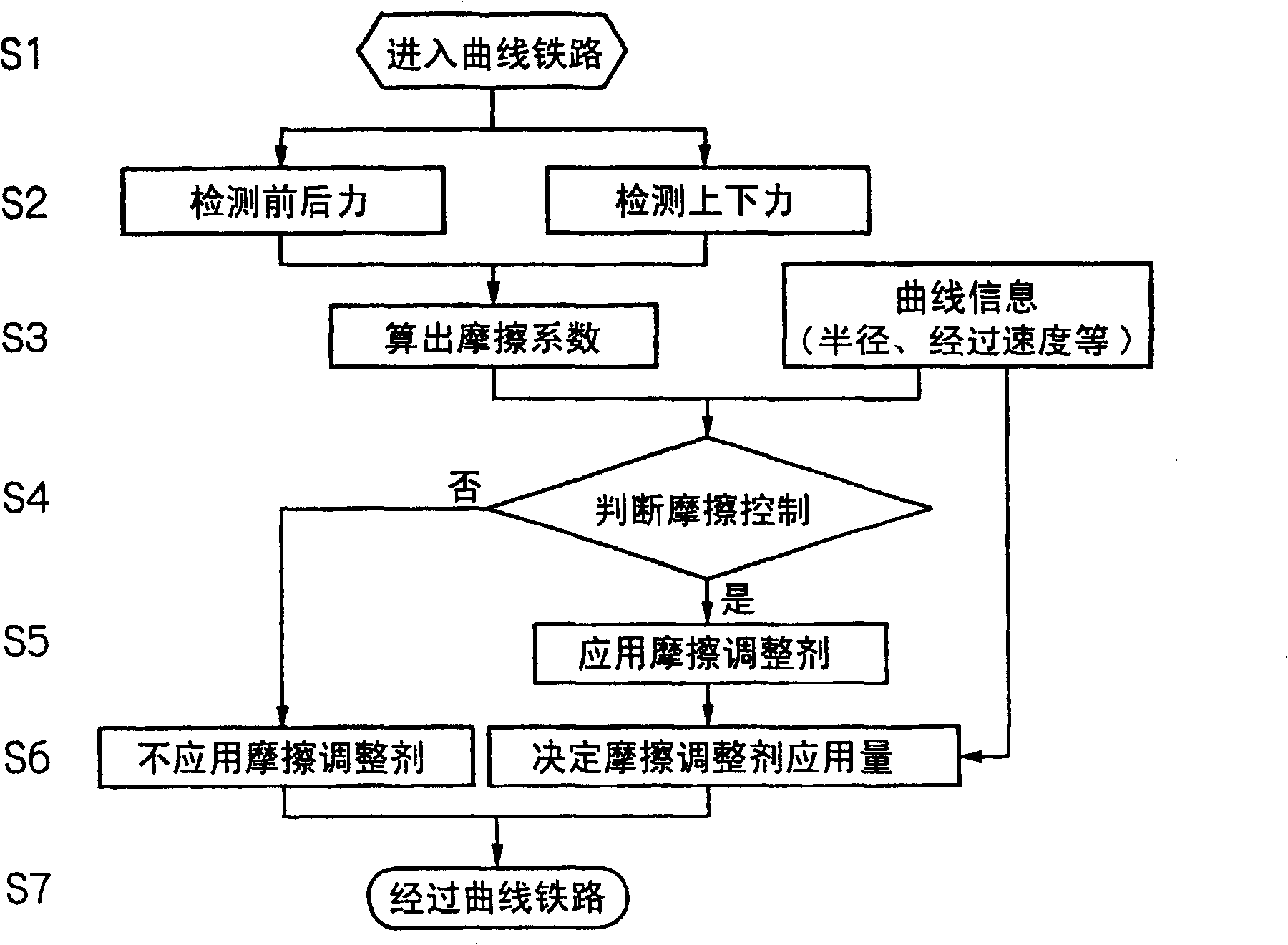
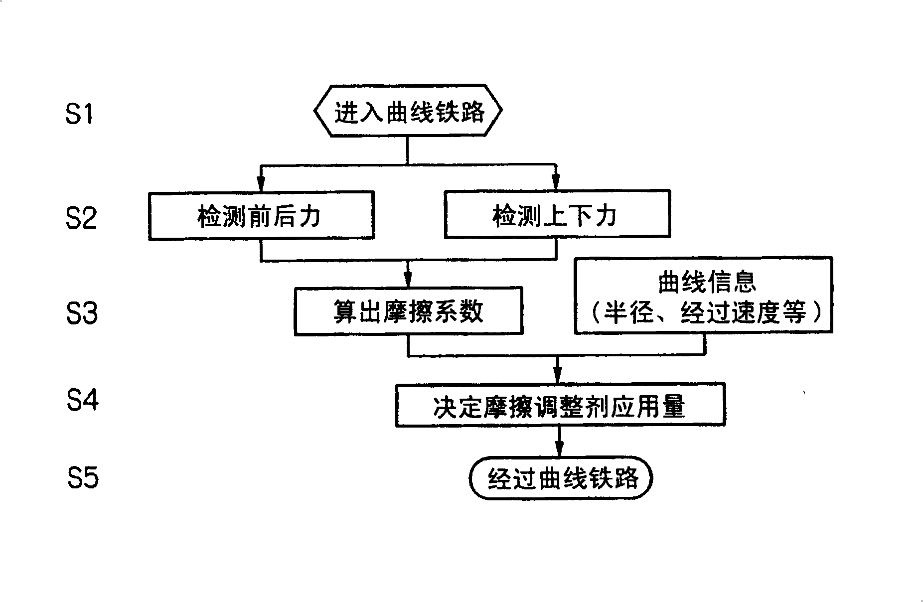
Friction between wheels and curved rails when a railway vehicle runs on the curved rails is controlled quantitatively and accurately. A friction control device (0) has a means (9) for detecting vertical force (P) acting on a wheel (2) positioned behind, relative to a railway vehicle advance direction, a truck (1) of the railway vehicle; a means (8) for detecting forward-backward force (T) acting on the wheel (2); a calculation means (7a) for calculating a friction coefficient between the wheel (2) and a curved rail (3) from both the detected vertical force (P) and forward-backward force (T); and an application control means (7b) for comparing, based on curve information, the calculated friction coefficient with a preset critical value, determining whether emission of an friction adjustment agent is needed, and issuing a command to a device (13) for emitting friction adjustment agent. A state of friction between the wheel (2) and the curved rail (3) can be grasped in real time, which enables appropriate control on the friction state.

Description

technical field [0001] The present invention relates to friction control devices for railway vehicles. In particular, the present invention relates to a friction control device for a railway vehicle for controlling the state of friction between the railway vehicle and a curved guide rail. Background technique [0002] Most of the modern railway vehicles, considering that the car body can be enlarged or can ensure good ride comfort due to the excellent followability to the guide rail, usually use the car body mounted on two axles. The bogie vehicle is composed of two bogie bogies (two axle bogie) with four wheels on the top. Of course, this bogie vehicle also runs on iron wheels guided by iron guide rails. [0003] However, especially in metropolitan areas, etc., since it is difficult to lay curved guide rails with a large radius of curvature, it is often necessary to lay curved guide rails with a small radius of curvature. If a railway vehicle runs on the curved guide rai...

Claims


Application Information

Patent Timeline
Patent Type & Authority Patents(China)
IPC IPC(8): B61K3/02G01N19/02B61C15/10
Inventor 中居拓自佐藤与志须田义大小峰久直松本耕辅荻野智久栗原纯远藤康信
Owner NIPPON STEEL CORP
Learn More