Method and apparatus for manufacturing color filter

A manufacturing method and a manufacturing device technology, which are applied in the field of color filter manufacturing and its devices, can solve the problems of inability to coat, increase the possibility of defective products, and increase the overall cost, and achieve the effect of suppressing uneven color

Active Publication Date: 2009-06-03
TORAY ENG CO LTD
View PDF2 Cites 0 Cited by
  • Summary
  • Abstract
  • Description
  • Claims
  • Application Information

AI Technical Summary

Problems solved by technology

[0009] In order to solve such a problem, it is conceivable to change the pitch of the ink nozzles by rotating the inkjet head, but there is a problem that it takes too much time for switching
[0010] In addition, the trend in recent years is the enlargement of the color filter and the enlargement of the glass substrate forming the color filter. In this way, when the size of the color filter and the glass substrate is increased, when the entire screen is adopted as in Patent Document 1, In the method of drawing in parallel with the main scan in a straight line, if the pixel arrangement is designed so that the pixel parts to be dyed in the same color are arranged in the same direction as the main scan direction, it is difficult to position the entire range of the main scan and make the slave inkjet The color material discharged from the nozzle is applied to the central part of the pixel area. In practice, there is a problem that the desired color material cannot be applied to a part of the pixel area. As a result, the possibility of manufacturing defective products increases.
[0011] When the method of Patent Document 2 is adopted, in order to cope with different screen sizes, the pitch is different for each screen size, so the probability that the ink nozzle and the central part of the pixel coincide is reduced. increase, the problem that the time required for overall coating becomes longer
[0012] In addition, as shown in FIG. 4 of Patent Document 2, the entire screen is drawn in parallel with the main scan in a straight line, and the pixel arrangement is designed so that the pixel parts to be colored in the same color are arranged in the same direction as the main scan direction. , when the size of the color filter and glass substrate is increased, it is difficult to perform positioning over the entire range of the main scan so that the color material discharged from the ink nozzle is applied to the center of the pixel area. In practice, there is a problem that it cannot Coating the desired color material to a part of the pixel area, as a result, the possibility of manufacturing defective products increases
[0013] In addition, the two moving mechanisms require high precision, so it will lead to an increase in the overall cost

Method used


Image

  • Method and apparatus for manufacturing color filter
  • Method and apparatus for manufacturing color filter
  • Method and apparatus for manufacturing color filter

Examples


Embodiment

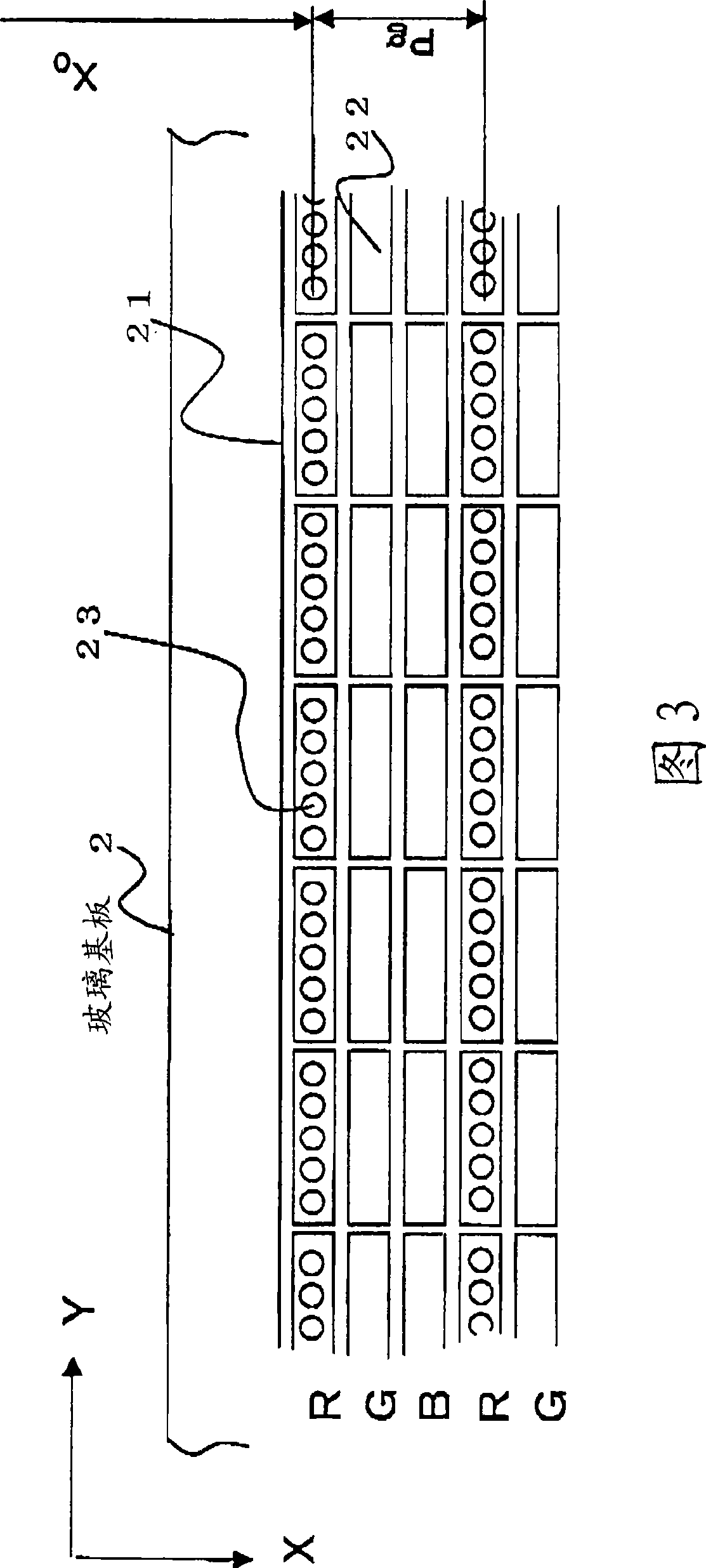
[0103] The nozzle width is 25400μm, the nozzle resolution is 1440dpi, the nozzle pitch P is 25400 / 1440=17.6μm, the pixel size is a=300μm, b=100μm, the coating area size is c=220μm, d=20μm, relative to the nozzle The number is N=c / P=220 / 17.6 12. The coating test was carried out under the conditions that the number M of droplets in the relative moving direction was 1, the coating amount in a pixel (filling amount in a pixel) V was 300p1, and the average Q of one droplet was 40p1.

[0104] Under this condition, the number n of remaining nozzles that satisfies the application amount in a pixel can be obtained by substituting a specific numerical value into Equation 1, and the number n of remaining nozzles is 4 or less.

[0105] As a result, the number i of combinations of ink jet nozzles 52 was 495.

[0106] Therefore, by using the ink nozzles 52 of 495 or less combinations (for example, 50 combinations) (for example, 50 combinations) (selection of the discharge state) to apply ...


PUM


Abstract

The present provides a method and apparatus for manufacturing color filter, the inventino is to apply a color material discharged from an ink jet nozzle on the center portion of a pixel region, irrespective of the screen sizes and size increase of a glass substrate. [MEANS FOR SOLVING PROBLEMS] A direction parallel to the longitudinal direction of an ink jet head bar (5) is set in the longitudinal direction of a pixel, and a relative moving direction of the inkjet head bar (5) is set in a direction orthogonally intersecting with the longitudinal direction of the pixel.

Description

technical field [0001] The present invention relates to a method of manufacturing a color filter on a glass substrate using an inkjet nozzle and an apparatus thereof. Background technique [0002] Conventionally, a method of producing a color filter on a glass substrate using an inkjet nozzle has been proposed (see Patent Document 1). [0003] Specifically, at least a transparent dye-absorbing layer is provided on the transparent substrate, and the area between pixels to be different colors is used as a non-staining area with anti-staining properties, and at the site where pixels to be the same color are adjacent to each other, A color filter is produced by applying a coloring agent to and dyeing the plurality of pixel portions to be the same color including the inter-pixel region without interruption. [0004] In addition, the method of main scanning and drawing the entire screen in parallel in a straight line is adopted. By arranging the pixel arrangement designed so that...

Claims


Application Information

Patent Timeline
Patent Type & Authority Applications(China)
IPC IPC(8): G02B5/20
CPCG02F1/133516G02B5/22B41J2202/09G02B5/201G02F1/1303G02F1/133512
Inventor 东野繁安田登志夫泉田信也上原淳一岩出卓
Owner TORAY ENG CO LTD
Why Eureka
Try Eureka