Scanning linear driver of displaying device and displaying device thereof

A driving device and scanning line technology, applied in the direction of static indicators, instruments, etc., can solve the problems of mutual interference of pixels, excessive power consumption of power supply, uneven brightness of the screen, etc., to solve the problem of excessive power consumption and avoid mutual interference of pixels Effect

Inactive Publication Date: 2009-01-21
TPO DISPLAY
View PDF3 Cites 0 Cited by
  • Summary
  • Abstract
  • Description
  • Claims
  • Application Information

AI Technical Summary

Problems solved by technology

[0009] The purpose of the present invention is to overcome the defects existing in the existing liquid crystal display, and provide a new scanning line drive device for the display. Interference between pixels, uneven brightness of the entire screen, or excessive power consumption, etc., making it more suitable for practical use
[0010] Another object of the present invention is to provide a display device. The technical problem to be solved is to make it possible to improve the mutual interference of pixels between two adjacent columns on the conventional panel, the uneven brightness of the entire picture or the power supply problem. Power consumption is too large and other issues, so it is more suitable for practical

Method used


Image

  • Scanning linear driver of displaying device and displaying device thereof
  • Scanning linear driver of displaying device and displaying device thereof
  • Scanning linear driver of displaying device and displaying device thereof

Examples


Embodiment Construction

[0083] In order to further explain the technical means and effects that the present invention adopts to achieve the intended purpose of the invention, below in conjunction with the accompanying drawings and preferred embodiments, the specific implementation methods, Structure, characteristic and effect thereof are as follows in detail.

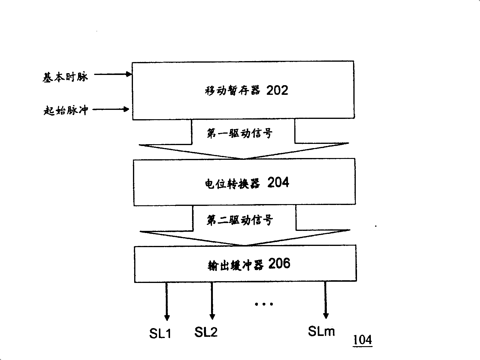
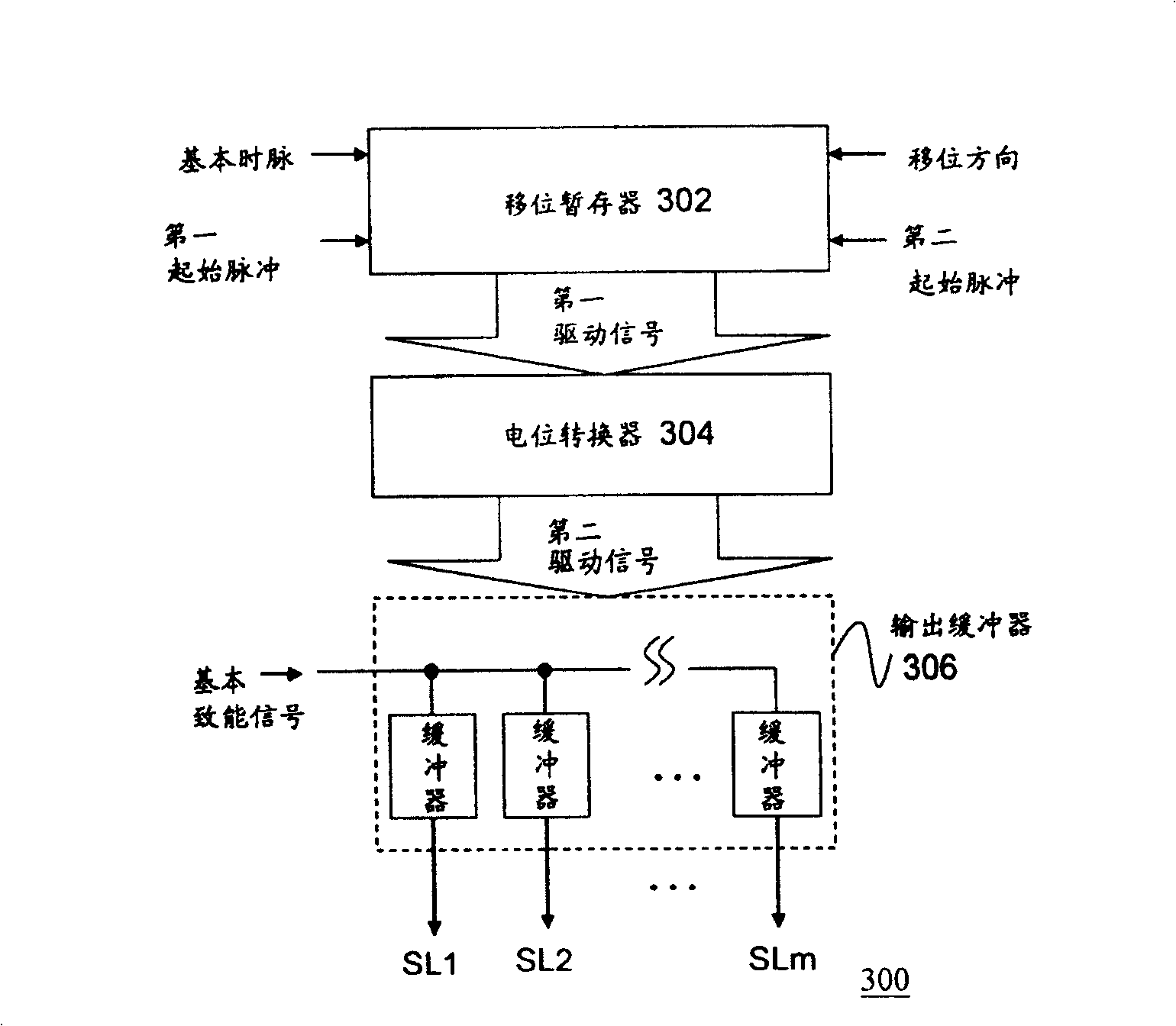
[0084] see image 3 Shown is a schematic diagram of a gate driver according to an embodiment of the present invention. Such as image 3 As shown, the gate driver 300 includes a shift register 302 , a level shifter 304 , and an output buffer 306 . The shift register 302 includes, for example, a conventional shift register or a bi-directional (bi-directional) shift register. Existing known shift registers include, for example figure 2 The shift register 202 shown in . image 3 The shift register 302 shown in is a bidirectional shift register, which receives a basic clock (clock), a shift direction (shift direction), and a first start pulse...


PUM


Abstract

A scan line driving device of display consists of scan line driver with multiple scanning lines for receiving basic time pulse and for outputting scan signal to each scanning line in sequence, control unit connected to said driver and scan line for receiving basic energizing signal and power supply. It is featured as controlling scan signal of the first scanning line by control unit when scan signal of the first scanning lines in scanning lines is used to drive display and generating scan signal of the first scanning line by basic energizing signal as well as generating scan signal of other scanning lines by power supply.

Description

technical field [0001] The invention relates to a display device, in particular to a scan line driving device of a display and a display device thereof. Background technique [0002] In recent years, liquid crystal display panels have gradually become the mainstream of display panels due to their advantages of light weight, thin size, large or small area, low operating voltage, power saving, and no radiation. In particular, for portable electronic devices, such as laptop screens, mobile phone screens, and personal digital assistant (Personal Digital Assistance, "PDA") display screens, etc., only liquid crystal screens can meet the requirements. Its demand, so the liquid crystal display panel has a trend of becoming more and more important. [0003] see figure 1 Shown is a schematic diagram of a conventional liquid crystal display. Such as figure 1 As shown, a conventional liquid crystal display 100 generally includes a liquid crystal panel 102 , a gate driver 104 and a s...

Claims


Application Information

Patent Timeline
Patent Type & Authority Patents(China)
IPC IPC(8): G09G3/36G02F1/133
Inventor 顾瑄峻陈维成林孝义
Owner TPO DISPLAY
Why Eureka
Try Eureka