Razor for hair cut and replacement razor for hair cut
A technology of razor and blade tip, which is applied in the field of replacement razors for hair cutting, and can solve problems such as difficult adjustment of hair H, difficulty in manual work, etc.
- Summary
- Abstract
- Description
- Claims
- Application Information
AI Technical Summary
Problems solved by technology
Method used
Image
Examples
Embodiment 1
[0104] The hair cutting razor 10 of Embodiment 1 will be described.
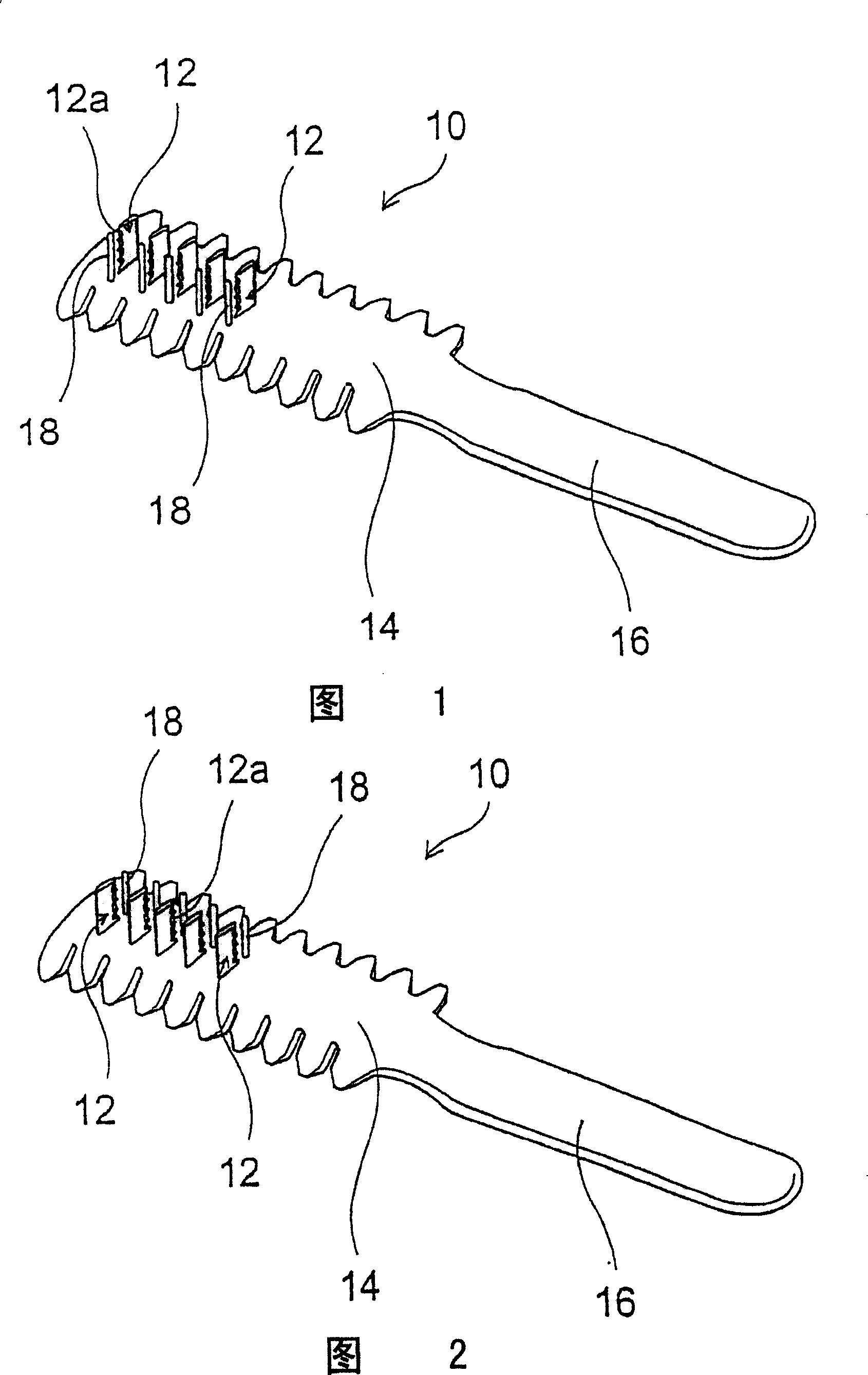
[0105] In this example, the cutter 12 that has cutter tip 12a is fixed on the base material 14 for hair cutting razor, and cutter 12 is juxtaposed, and each cutter tip 12a of five cutters 12 is the same direction, and cutter tip 12a is towards the left side in the figure ( Refer to Figure 1).
[0106] Furthermore, the details will be further described, but the example shown in FIG. 1 is a preferred example when cutting the hair from the right side to the neck side at the back of the scalp hair of the head T, so it can be said that the right hand is used.
[0107] On the other hand, the example shown in FIG. 2 can be said to be symmetrical to the example in FIG. 1 , and the blade tip 12 a is for the left hand facing the right side of the drawing.
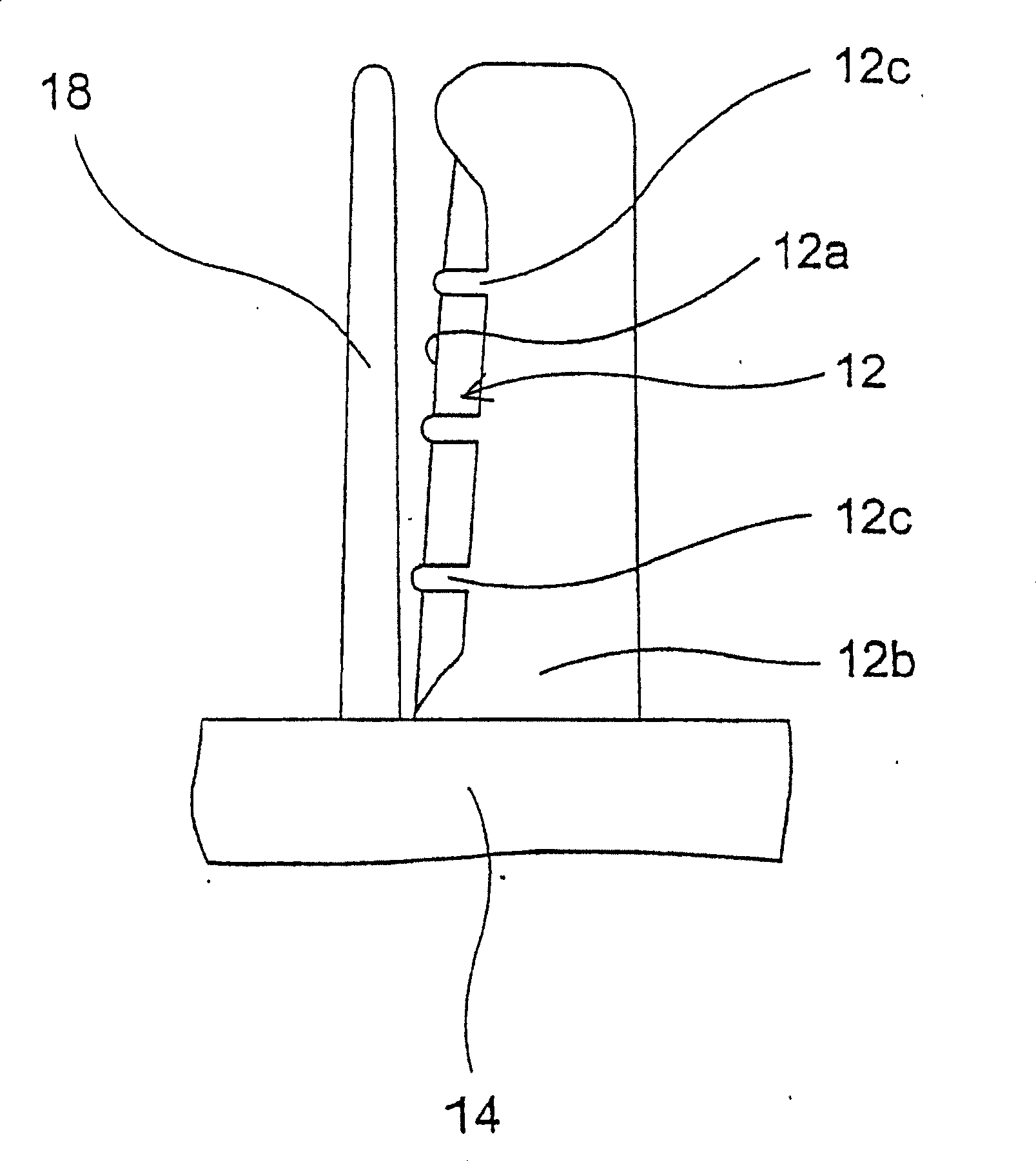
[0108] The basic configuration of these examples is that the blades 12 each having a cutting edge 12 a are erected on the base material 14 for a hair cutting razo...
Embodiment 2
[0129] Embodiment 2 will be described.
[0130] refer to Figure 7 This form 2 will be described.
[0131] This example differs from Embodiment 1 in essence of the invention, so only the configurations that are different in principle will be described, and the description of the above-mentioned Embodiment 1 will be referred to for the same configurations.
[0132] On the base material 14 for hair cutting and razor having a handle 16, six blades 12 having a blade tip 12a stand side by side.
[0133] All the cutting edges 12a of the cutters 12 in Embodiment 1 face the same direction, but in this example, among the cutting edges 12a of the six cutting tools 12, the facings of the adjacent cutting edges 12a are arranged in different directions.
[0134] The arrangement directions of these blade edges 12a are different from each other by 180 degrees in the illustrated example, but are not limited to 180 degrees.
[0135] As in the first embodiment, a pin-shaped control member 18...
Embodiment 3
[0138] Embodiment 3 will be described.
[0139] This example differs from Embodiment 1 in essence of the invention, so only the configurations that are different in principle will be described, and the description of the above-mentioned Embodiment 1 will be referred to for the same configurations.
[0140] refer to Figure 8 , Figure 9 This example will be described. In the above-mentioned first embodiment, the cutters 12 are arranged in parallel without inclination. Set at the upper right of the surface, or set at the upper left of the drawing with reference line L as the boundary (refer to Figure 8 , Figure 9 ).
[0141] Therefore, this embodiment is the same as Embodiment 1, and there are two kinds of use for the right hand and for the left hand during use.
[0142] When the hair cutting razor 10 is used, the angle of the blade tip 12a relative to the hair H often varies depending on the user's preference, the part where the hair H is combed, and the part where the ...
PUM
 Abstract
Description
Claims
Application Information
 - R&D
- Intellectual Property
- Life Sciences
- Materials
- Tech Scout
- Unparalleled Data Quality
- Higher Quality Content
- 60% Fewer Hallucinations
Browse by: Latest US Patents, China's latest patents, Technical Efficacy Thesaurus, Application Domain, Technology Topic, Popular Technical Reports.
© 2025 PatSnap. All rights reserved.Legal|Privacy policy|Modern Slavery Act Transparency Statement|Sitemap|About US| Contact US: help@patsnap.com


