
Camera with built-in flash lamp type

A flashlight and camera technology, applied in optics, instruments, photography, etc., can solve the problems of irregular reflection, difficult to extend the distance between the flashlight frame 102 and the flashlight component 201, and cannot be alleviated, so as to achieve the effect of reducing irregular reflection

Inactive Publication Date: 2009-04-01
PANASONIC CORP
View PDF5 Cites 0 Cited by
  • Summary
  • Abstract
  • Description
  • Claims
  • Application Information

AI Technical Summary

Problems solved by technology

However, in this built-in flash camera, the support rod 101, the driving rod 203, and the C-shaped link 204 are arranged inside the camera bodies 100, 200, so it is difficult to extend the distance from the camera body 100, 200 to the protruding position. The problem of the distance between the flash frame 102 and the flash unit 201
[0018] And no matter what kind of built-in flash camera, they all have a structure that protrudes from the retracted position to almost directly above when the protruding position is in the protruding position. Therefore, there are also easy factors for the light emission from the light emitting unit of the flash light emitting unit 102a and the flash unit 201. The problem of irregular reflection caused by components such as the lens barrel located in the front center of the camera body 100, 200
[0019] In addition, even if the flash housing 102 and the flash unit 201 are protruded from the camera body 100, 200, the flash housing 102 and the flash unit 201 cannot be completely removed from the camera body 100, 200 in order to prevent the wiring part from being exposed. From this point of view, it is also difficult to set the flash housing 102 and the flash unit 201 too high in a protruding posture.
[0020] And no matter what kind of camera with a built-in flash, under the protruding posture, the flash light emitting part 102a and the flash light unit 201 are all arranged to face the front, and the light from the light emitting part directly illuminates the imaging object in front, so sometimes when emitting light, There is a problem that the shadow of the object behind the camera is clearly captured, and there is a problem that this defect cannot be alleviated

Method used


Image

  • Camera with built-in flash lamp type
  • Camera with built-in flash lamp type
  • Camera with built-in flash lamp type

Examples


Embodiment Construction

[0069] (Embodiment 1)

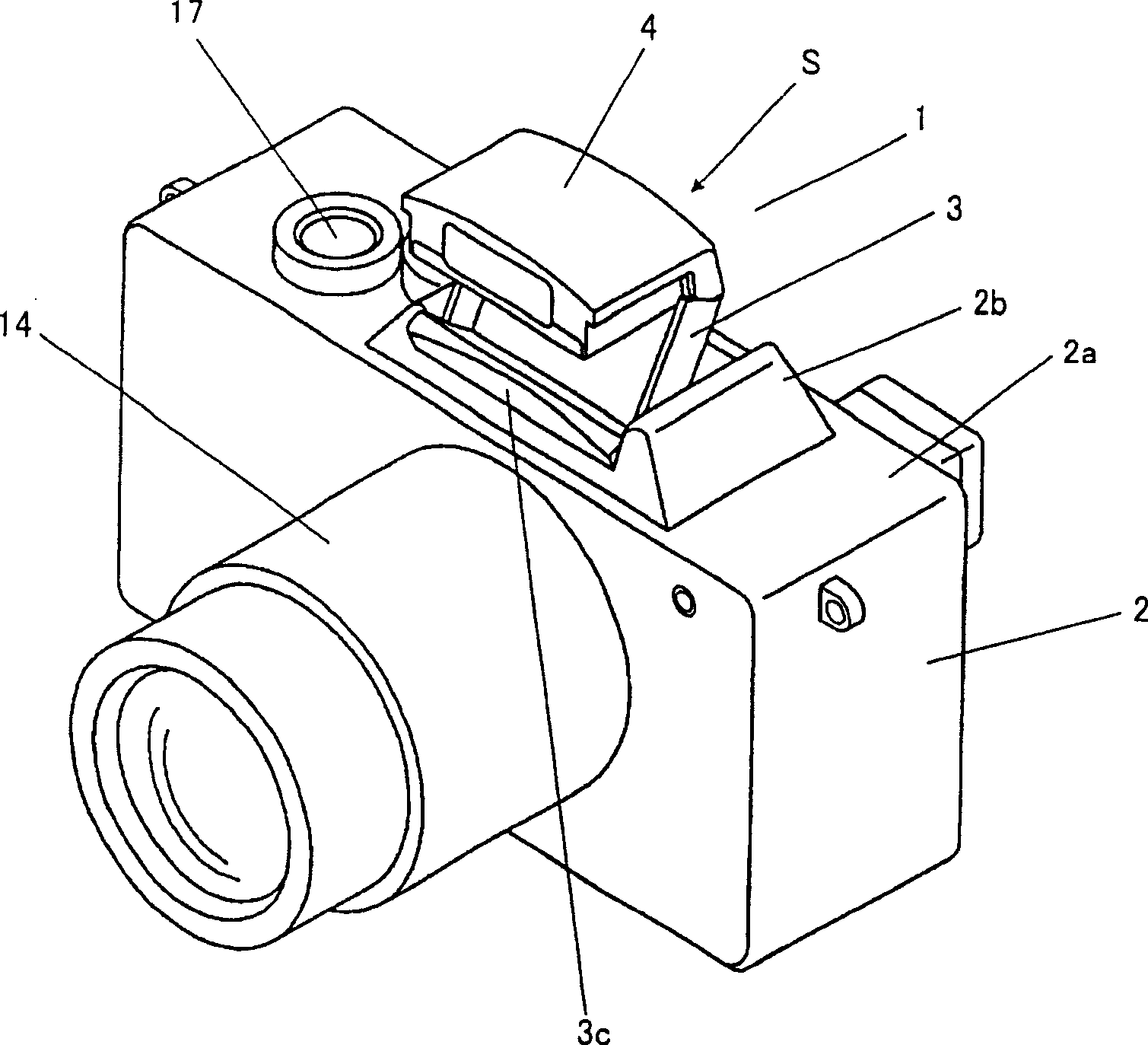
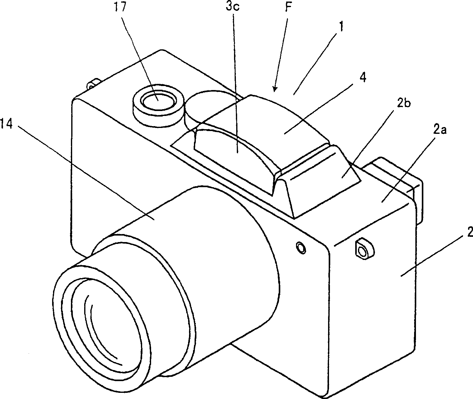
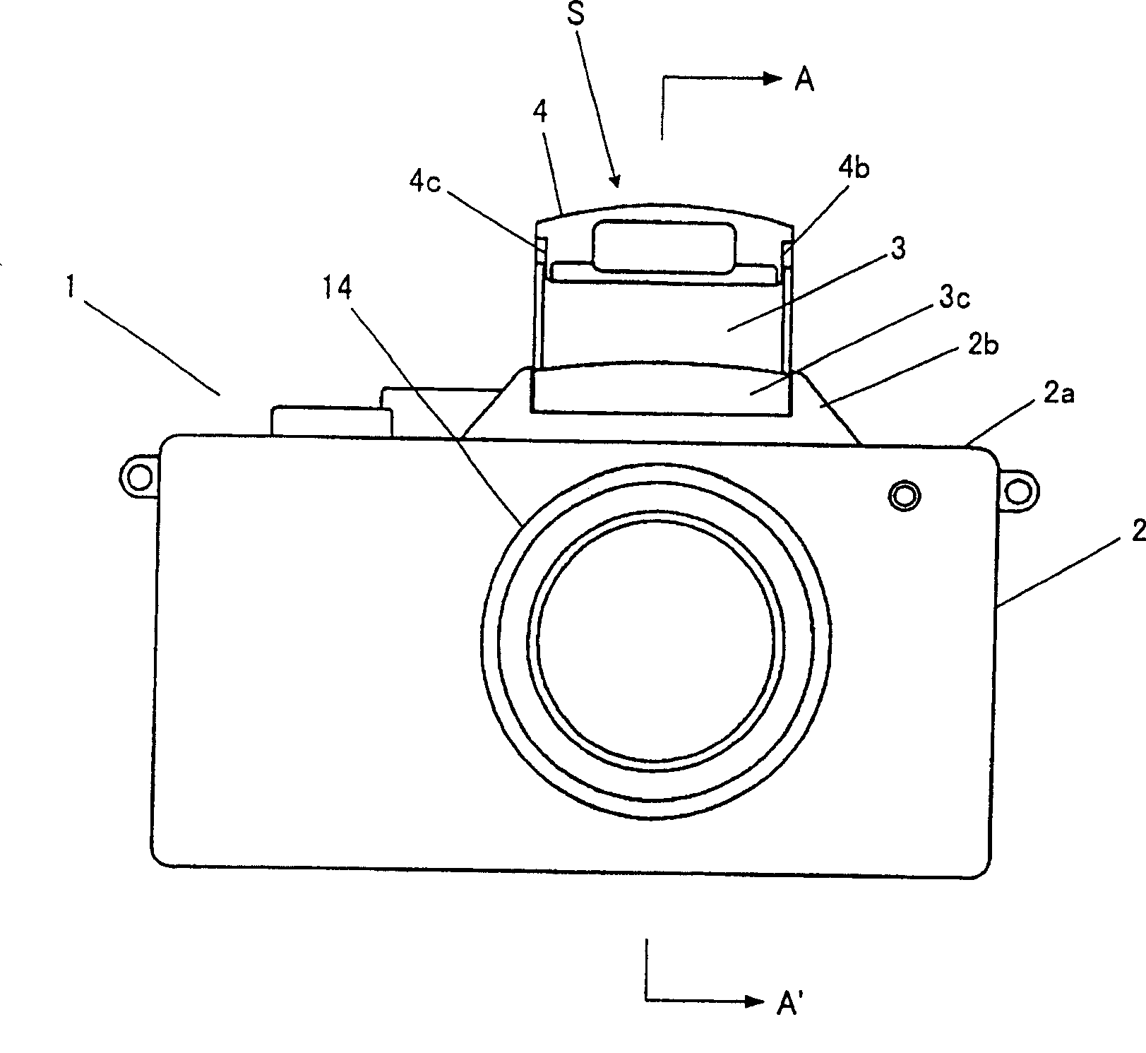
[0070] figure 1 and figure 2 It is a perspective view showing a built-in flash camera according to Embodiment 1 of the present invention, image 3 is its front view, Figure 4 and Figure 6 yes means image 3 An enlarged view of the main part of the section of the line A—A', Figure 5 It is an enlarged side view showing a main part of the built-in flash camera according to Embodiment 1 of the present invention. and figure 1 , Figure 3 ~ Figure 5 , indicating the state when the flash housing 4 is in the second position S, figure 2 and Figure 6 It shows the state when the flash housing 4 is in the first position F. Here, the term "first position" and "second position" used in this specification and claims is meant to indicate that the distance from the flash housing 4 to the camera body 2 when it is at the second position is greater than the distance when it is at the first position. The terms of positional relationship are used.

[0071...


PUM


Abstract

This camera with built-in stroboscope is provided with a camera body 2, a holder 3 which has a first turning part 11 and a second turning part 12 and is pivotally supported to the camera main body 2 to be freely rotatable in the first turning part 11 and a stroboscope casing 4 whose side face is pivotally supported to the holder 3 to be freely rotatable in the second turning part 12, a first locking part 15 which locks the holder 3 in a second position and a second locking part 16 which locks the strobe casing 4 in the second position.

Description

technical field [0001] The present invention relates to a built-in flash camera, and more particularly to a built-in flash camera with a pop-up mechanism capable of moving a flash housing mounted on a camera body between a first position and a second position. Background technique [0002] Conventionally, in digital still cameras and film-sensitive compact cameras, cameras with a built-in flash are generally popularized by incorporating a flash housing with a flash light-emitting unit that emits auxiliary light when taking pictures. . [0003] In this built-in flash camera, in addition to the model that can open and close the lens barrel, there are also models that have a flash housing installed in the camera body that can move between the first position and the second position. Reload mechanism. [0004] In general, a built-in flash camera of a type having a pop-up mechanism has a problem of increasing the overall size of the camera in order to install the pop-up mechanis...

Claims


Application Information

Patent Timeline
Patent Type & Authority Patents(China)
IPC IPC(8): G03B15/05G03B15/03
CPCG03B15/03
Inventor 氏兼幸和才木淳
Owner PANASONIC CORP
Learn More