Parallel type electromagnetic flowmeter with dual excitations
An electromagnetic flowmeter, dual excitation technology, applied in the application of electromagnetic flowmeter to detect fluid flow, volume/mass flow generated by electromagnetic effect, etc., can solve the problem that there is no ideal method for quantitative dynamic monitoring of fluid conductivity or internal resistance, etc. question
- Summary
- Abstract
- Description
- Claims
- Application Information
AI Technical Summary
Problems solved by technology
Method used
Image
Examples
Embodiment 1
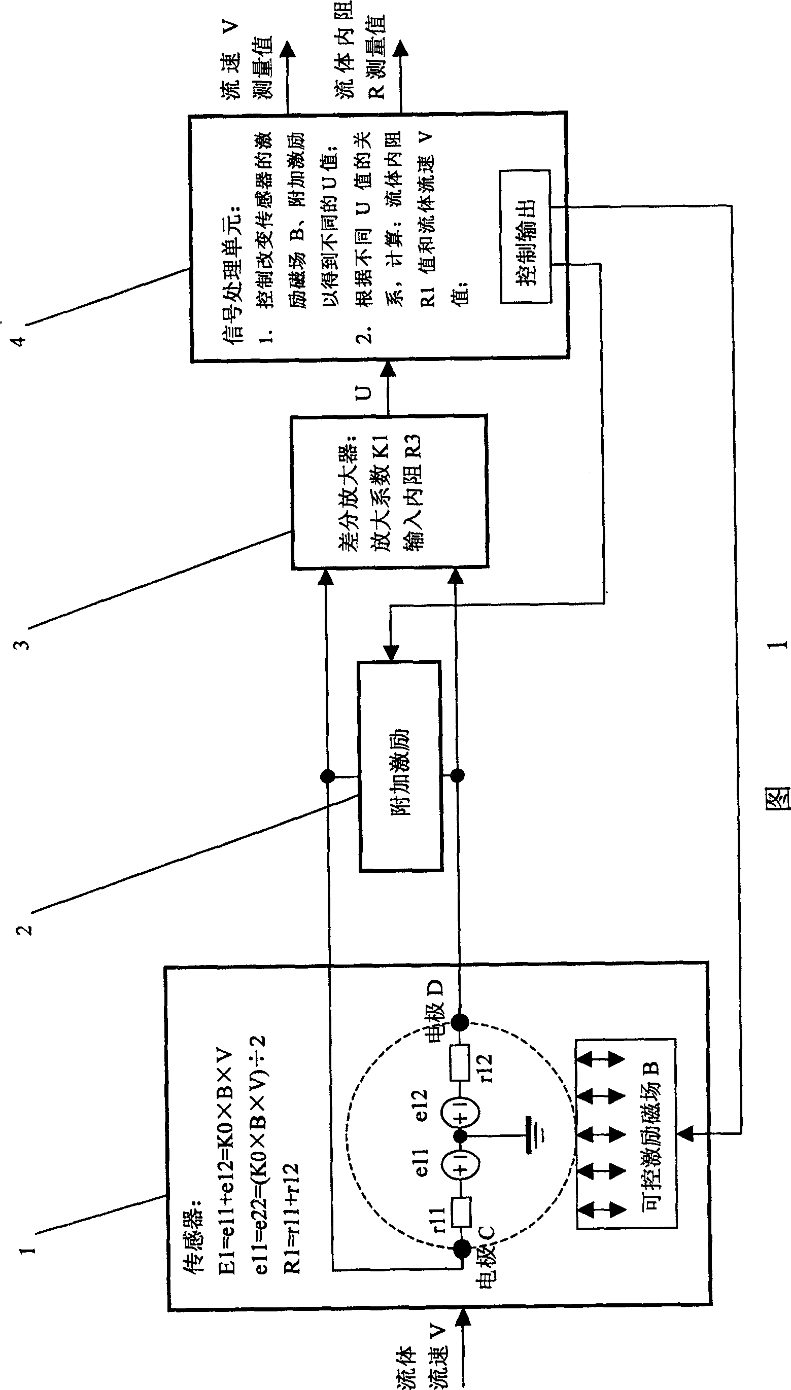
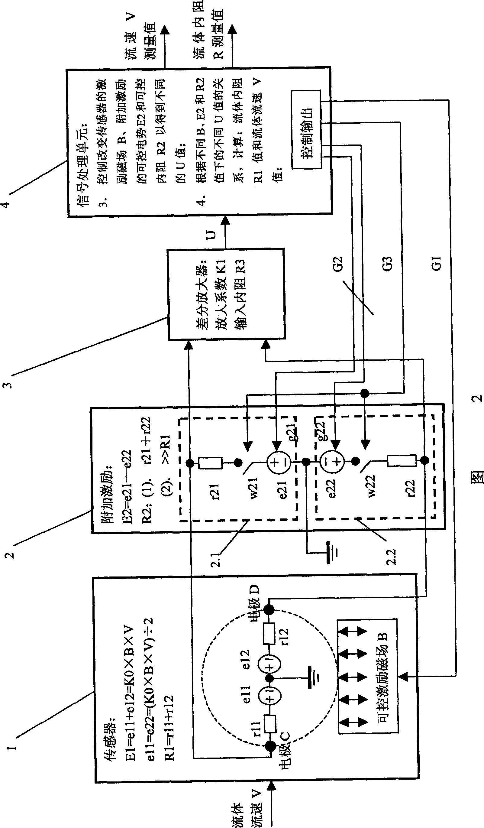
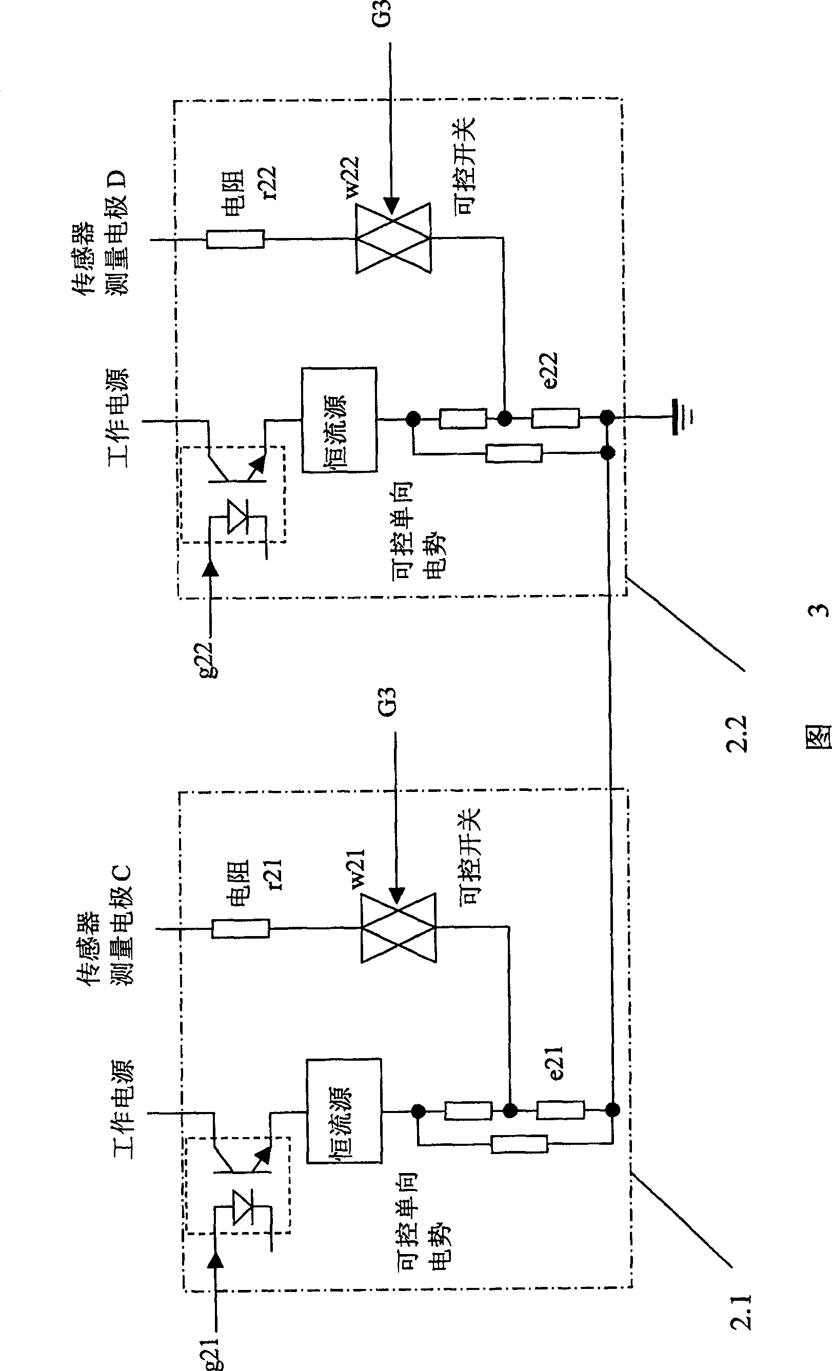
[0068] Embodiment 1: Referring to Fig. 1, this parallel double excitation electromagnetic flowmeter includes a sensor 1 having an excitation magnetic field B to form a fluid cutting magnetic force line to generate an induced potential, a differential amplifier 3 having an input internal resistance R3 and a signal amplification factor K1 and A signal processing unit 4, the sensor 1 has two measuring electrodes C and D for the fluid, the two measuring electrodes C and D are connected to the input of the differential amplifier 3, and the output U of the differential amplifier 3 is connected to the signal processing unit 4; the fluid The electrical conductivity makes two electrodes C and D have fluid internal resistance R1, and the electrodes C and D of sensor 1 have induced potential E1=K0×B×V under the fluid velocity V, K0 is the coefficient of sensor (1); It is characterized in that An additional excitation 2 is connected in parallel at both ends of the electrodes C and D of the...
Embodiment 2
[0089] Embodiment 2: This embodiment is basically the same as the above embodiment, the difference is: see Figure 4 and Figure 5, the above additional excitation 2 is composed of equivalent internal resistance R2 and controllable potential E2 connected in series, corresponding to the difference The output U of amplifier 3 has:
[0090] U = K 1 × E 1 × R 50 R 1 + R 50 + E 2 × R 40 R 2 + R 40 , in R 40 = R 1 × R ...
Embodiment 3
[0105] Embodiment 3: This embodiment is basically the same as Embodiment 1, the difference is: referring to Fig. 6 and Fig. 7, the above-mentioned additional excitation 2 is only composed of controllable internal resistance R2, corresponding to the output U of the differential amplifier 3:
[0106] U = K 1 × E 1 × R 50 R 1 + R 50 , in R 50 = R 2 × R 3 R 2 + R 3 ;
[0107]The signal processing unit 4 has a control output G3 to control the controllable internal resistance R2 of the addition...
PUM
 Abstract
Description
Claims
Application Information
 - R&D
- Intellectual Property
- Life Sciences
- Materials
- Tech Scout
- Unparalleled Data Quality
- Higher Quality Content
- 60% Fewer Hallucinations
Browse by: Latest US Patents, China's latest patents, Technical Efficacy Thesaurus, Application Domain, Technology Topic, Popular Technical Reports.
© 2025 PatSnap. All rights reserved.Legal|Privacy policy|Modern Slavery Act Transparency Statement|Sitemap|About US| Contact US: help@patsnap.com


