Headlight irradiation position regulator

A technology for adjusting devices and headlights, which is applied to signal devices, transportation and packaging, and vehicle components, and can solve problems such as adjusting headlights and affecting vehicles coming ahead

Inactive Publication Date: 2009-06-03
T Y C BROTHER IND CO LTD
View PDF6 Cites 0 Cited by
  • Summary
  • Abstract
  • Description
  • Claims
  • Application Information

AI Technical Summary

Problems solved by technology

However, it is known that the headlights of vehicles cannot adjust the position of the headlights according to the tilt angle of the vehicle body, resulting in glare and affecting the vehicles ahead. Therefore, it is really a big concern for driving safety.

Method used


Image

  • Headlight irradiation position regulator
  • Headlight irradiation position regulator
  • Headlight irradiation position regulator

Examples


Embodiment Construction

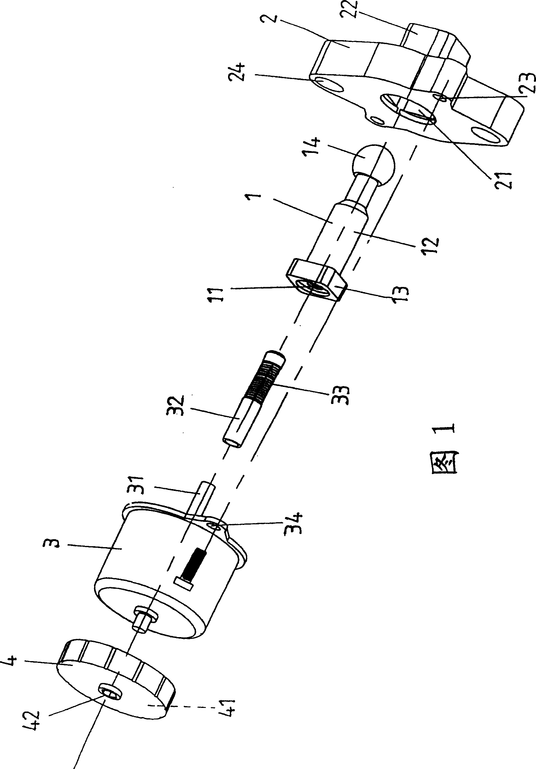
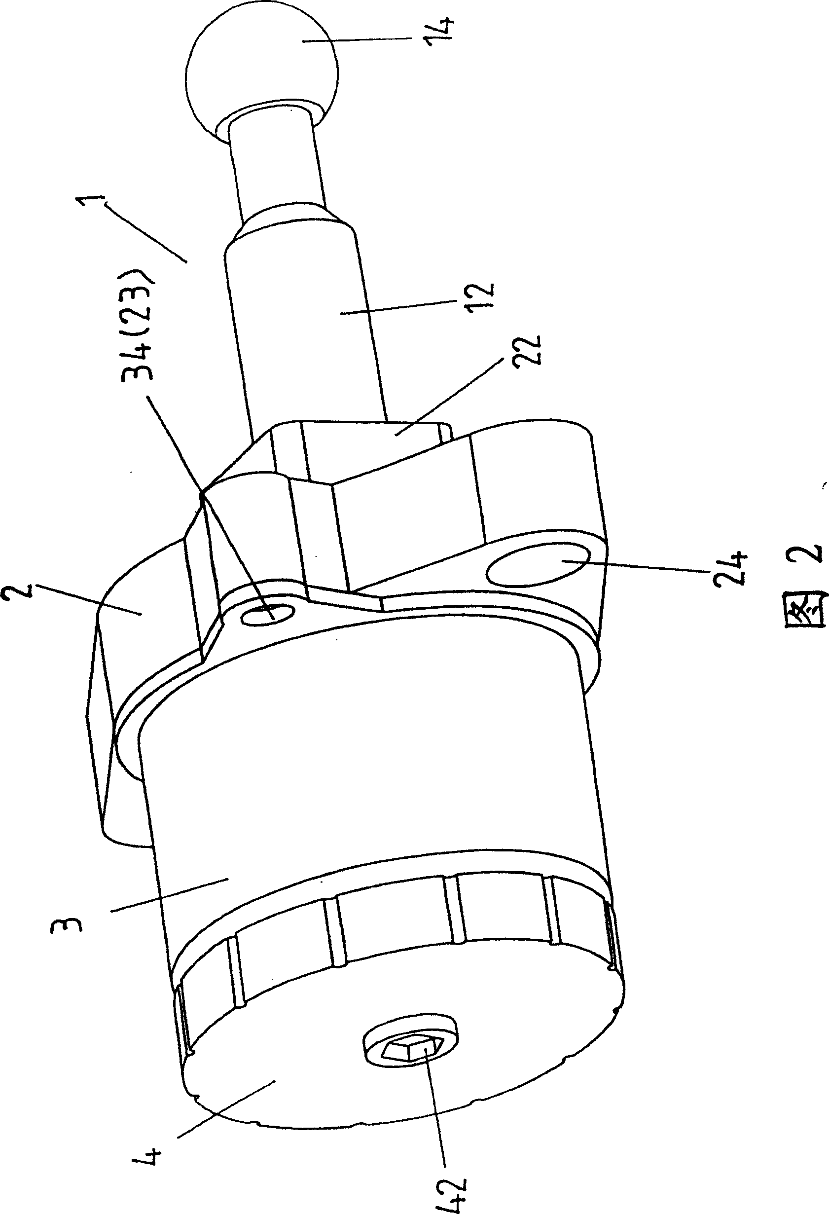
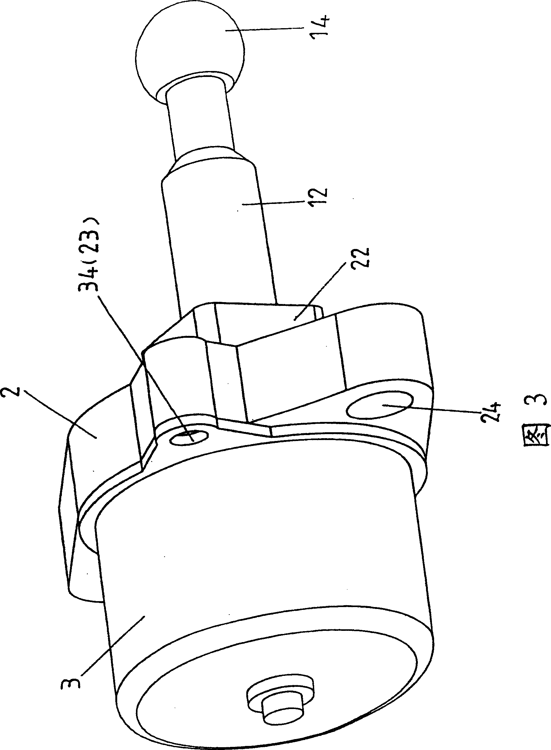
[0029] First of all, please refer to Fig. 1 and Fig. 2, which are schematic diagrams of the headlight irradiation position adjustment device of the present invention. The adjustment device A mainly includes an adjustment rod 1, a motor seat 2, a motor 3 and an adjustment wheel 4. in:

[0030] The adjustment rod 1 is provided with an internal thread section 11, which is formed by an external screw rod 12 with a fixed part 13 on one end and a top catch part 14 on the other end;

[0031] The symmetrical central part of the motor base 2 is provided with an accommodating space 21, and one end is provided with a connection end 22, which can accommodate the fixed part 13 fixedly connected to the adjustment rod 1, and a positioning hole 23 is provided on the corresponding two ends of the motor base 2. , and a fixing hole 24 is provided on the corresponding two ends;

[0032] The shaft center 31 of the motor 3 is fixed in the inner screw rod 32, and an external thread segment 33 corre...


PUM


Abstract

The headlight irradiation position regulator includes mainly one regulating screw rod with pushing and stopping part on one end, one motor seat with holding space in the middle part, one motor with axle in one screw rod with regulating section, and one regulating wheel connected to the motor axle and with regulating hole. The headlight irradiation position regulator is driven electrically or manually to regulate the headlight irradiation position.

Description

technical field [0001] The invention relates to a device for adjusting the irradiation position of a headlight, in particular to a device for adjusting the irradiation position of a headlamp which can be adjusted electrically or manually to achieve a translation and repeated action. Background technique [0002] The development of transportation means has brought considerable convenience to life so far. In addition to the convenience of movement, the consideration of relative safety is the most important. When the vehicle is running, facing the daily weather and road conditions, the lighting equipment of the vehicle is an important equipment to maintain the safety of the driver. [0003] The headlights installed in front of the vehicle can illuminate the road conditions in front of the vehicle and make the third driver know the conditions of the vehicles ahead. However, it is known that the headlights of vehicles cannot adjust the irradiation position of the headlights acco...

Claims


Application Information

Patent Timeline
Patent Type & Authority Patents(China)
IPC IPC(8): B60Q1/06
Inventor 郭明山陈韦任
Owner T Y C BROTHER IND CO LTD
Why Eureka
Try Eureka