Railway turnout snow melting locking frame heating mechanism

A technology of heating mechanism and locking frame, which is applied in track cleaning, construction, cleaning methods, etc., can solve the problems of low thermal efficiency, lack of snow removal, high labor intensity, etc., and achieve strong corrosion resistance, aging resistance, and convenience Installation and maintenance, the effect of increasing the heat transfer area

Pending Publication Date: 2020-06-12
XIAN RAILWAY SIGNAL
View PDF0 Cites 0 Cited by
  • Summary
  • Abstract
  • Description
  • Claims
  • Application Information

AI Technical Summary

Problems solved by technology

[0002] In the cold regions of northern my country, especially in the northeast region, the continuous heavy snow in winter covers the outer locking device of the turnout, causing the locking frame and locking rod, locking iron and locking hook, locking frame and locking hook to freeze At the same time, the external locking device cannot work normally, and the turnout cannot be flexibly switched, so that the train is in an unsafe state, causing common accidents such as missed trains and delays, especially for high-speed railways.
At present, the main method of melting snow at the outer locking device of the domestic turnout is to install a heating plate under the locking frame. Since the heating heat is transmitted through thermal radiation, the thermal efficiency is low and the effect is negligible. Especially in the case of strong winds, a large amount of heat will be lost Lost in the air, basically does not play any role in snow removal
Therefore, heating tools such as blowtorches and hot air guns can only be used to manually remove snow and ice at the outer locking device. The labor intensity is very high, which is both troublesome and unsafe. Therefore, there is an urgent need for a snow and ice removal device with high heating efficiency to effectively heat the outer locking device.

Method used


Image

  • Railway turnout snow melting locking frame heating mechanism
  • Railway turnout snow melting locking frame heating mechanism
  • Railway turnout snow melting locking frame heating mechanism

Examples


Embodiment Construction

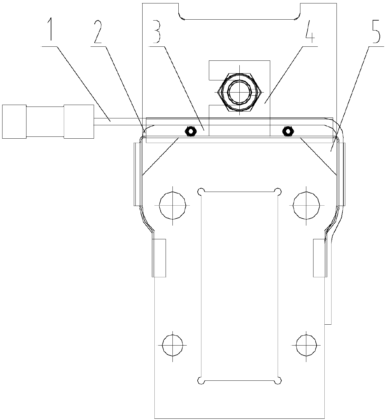
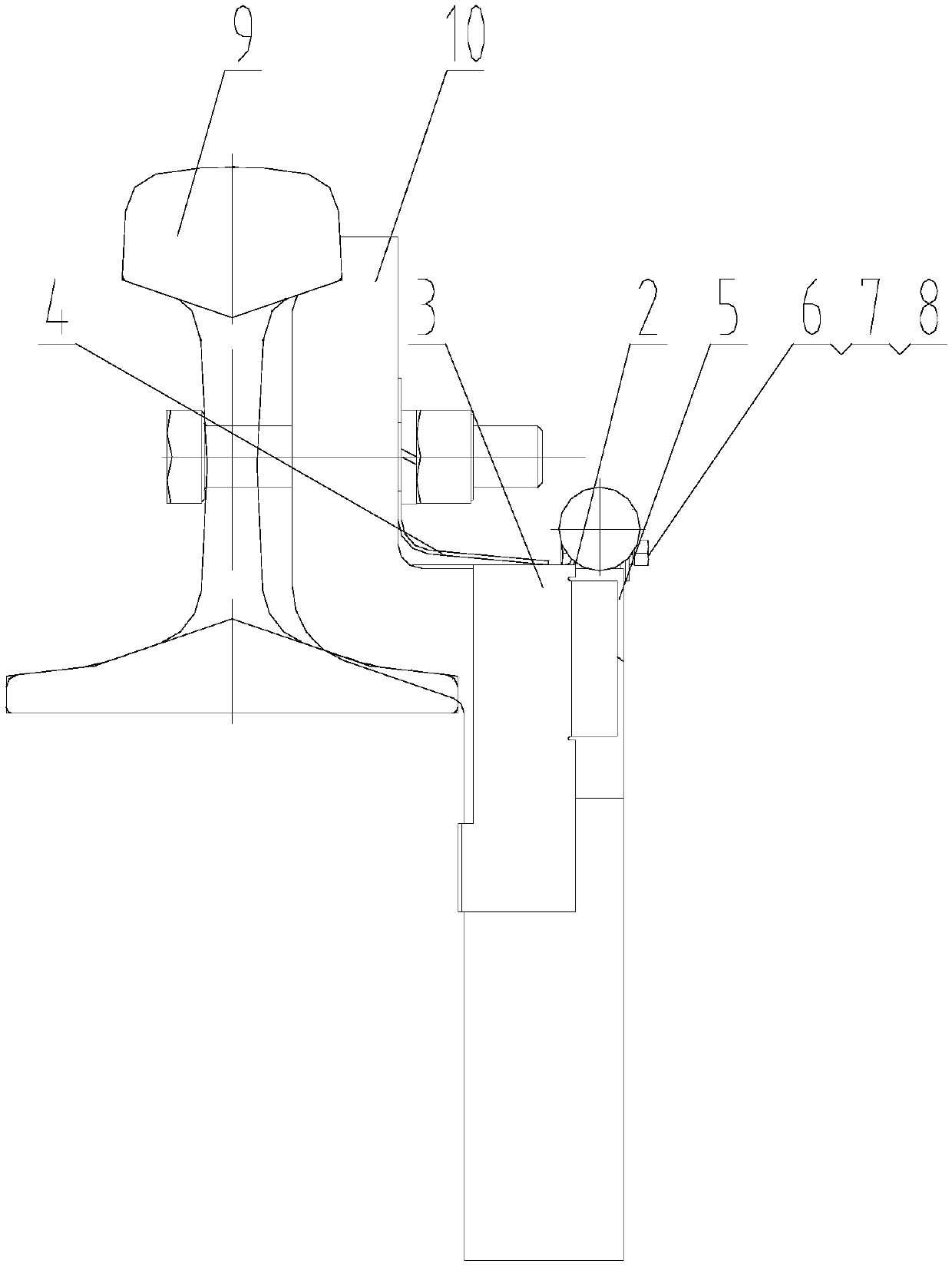
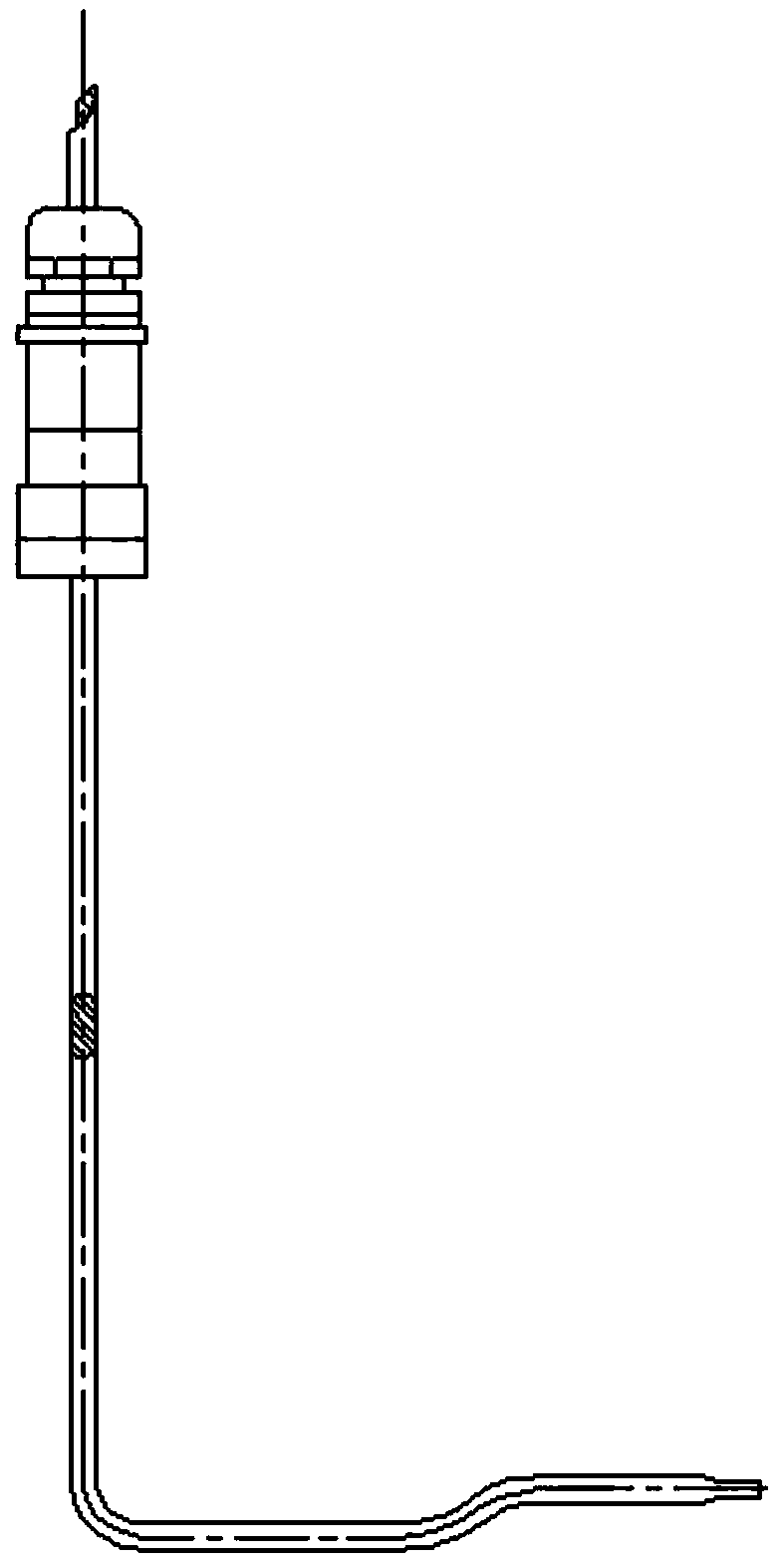
[0023] As shown in Figure 1, the present invention relates to a heating mechanism for a railway turnout snow melting locking frame, which is characterized in that it includes an L-shaped 180W electric heating element 1, an aluminum alloy heat conducting pad 2, an elastic clamp 3, an elastic pressing piece 4, Aluminum alloy triangular filling block 5, fastener group 6-8, railway turnout 9, locking frame 10; the locking frame 10 is connected with the railway turnout 9 through bolts and nuts, and the locking frame 10 has a On the extension table, the elastic fixture 3 is stuck on both sides of the extension table. The elastic fixture 3 is connected with the elastic pressing piece 4 and the aluminum alloy thermal pad 2 at the same time. One end of the elastic pressing piece 4 is fixed on the locking frame 10 and the railway switch 9 In the connected bolts and nuts, the L-shaped 180W electric heating element 1 is connected through the elastic pressing piece 4, and the fastener group...


PUM


Abstract

The invention relates to a railway turnout snow melting locking frame heating mechanism. The railway turnout snow melting locking frame heating mechanism is characterized by comprising an electric heating element (1), an aluminum alloy heat conduction cushion block (2), an elastic clamp (3), an elastic pressing piece (4), an aluminum alloy triangular filling block (5), a railway turnout (9) and alocking frame (10); and the locking frame (10) is connected with a railway turnout (9) through bolts and nuts, the locking frame (10) is provided with an extension table at the lower end of the bolt and the nut, the elastic clamps (3) are clamped on two sides of an epitaxial platform, the elastic clamps (3) are simultaneously clamped with the elastic pressing sheets (4) and the aluminum alloy heatconduction cushion blocks (2), one end of the elastic pressing sheet (4) is fixed in a bolt and a nut for connecting the locking frame (10) and a railway turnout (9), and the L-shaped 180W electric heating element (1) is connected through the elastic pressing sheets (4). The railway turnout snow melting locking frame heating mechanism is high in heating efficiency, good in safety and convenient to use and install.

Description

technical field [0001] The invention is suitable for heating the locking frame of various models of external locking track devices matched with all domestic turnouts, and in particular relates to a heating mechanism for melting snow locking frames of railway turnouts. Background technique [0002] In the cold regions of northern my country, especially in the northeast region, the continuous heavy snow in winter covers the outer locking device of the turnout, causing the locking frame and locking rod, locking iron and locking hook, locking frame and locking hook to freeze Together, the external locking device cannot work normally, and the turnout cannot be flexibly converted, so that the train is in an unsafe state, causing common accidents such as missed trains and delays, especially for high-speed railways. At present, the main method of melting snow at the outer locking device of the domestic turnout is to install a heating plate under the locking frame. Since the heating h...

Claims


Application Information

Patent Timeline
Patent Type & Authority Applications(China)
IPC IPC(8): E01H8/08
CPCE01H8/08
Inventor 南长江何建峰
Owner XIAN RAILWAY SIGNAL
Why Eureka
Try Eureka