Supercharge Your Innovation With Domain-Expert AI Agents!

Electrical connector

A technology of electrical connectors and wires, which is applied in the direction of connections, circuits, and parts of connecting devices. It can solve problems such as difficulties in electrical connectors, difficult level differences, etc., and achieve enhanced smooth insertion, prevention of mis-insertion, and anti-reverse insert effect

Active Publication Date: 2009-10-14
TYCO ELECTRONICS JAPAN GK
View PDF8 Cites 0 Cited by
  • Summary
  • Abstract
  • Description
  • Claims
  • Application Information

AI Technical Summary

Problems solved by technology

But this is still not enough, because the leading edge of the small protrusion tends to scrape against the inner wall of the housing, allowing reverse insertion
[0009] Also, even when the contacts are inserted in the correct orientation, it can be difficult to get the contacts smoothly across the level difference between the large diameter area near the jack opening and the small diameter area at the back of the jack opening
This is especially difficult when electrical connectors are attached to wires with a cross-section of 0.22 to 0.5 mm

Method used


Image

  • Electrical connector
  • Electrical connector
  • Electrical connector

Examples


Embodiment Construction

[0037] Embodiments of the present invention will be described below with reference to the drawings.

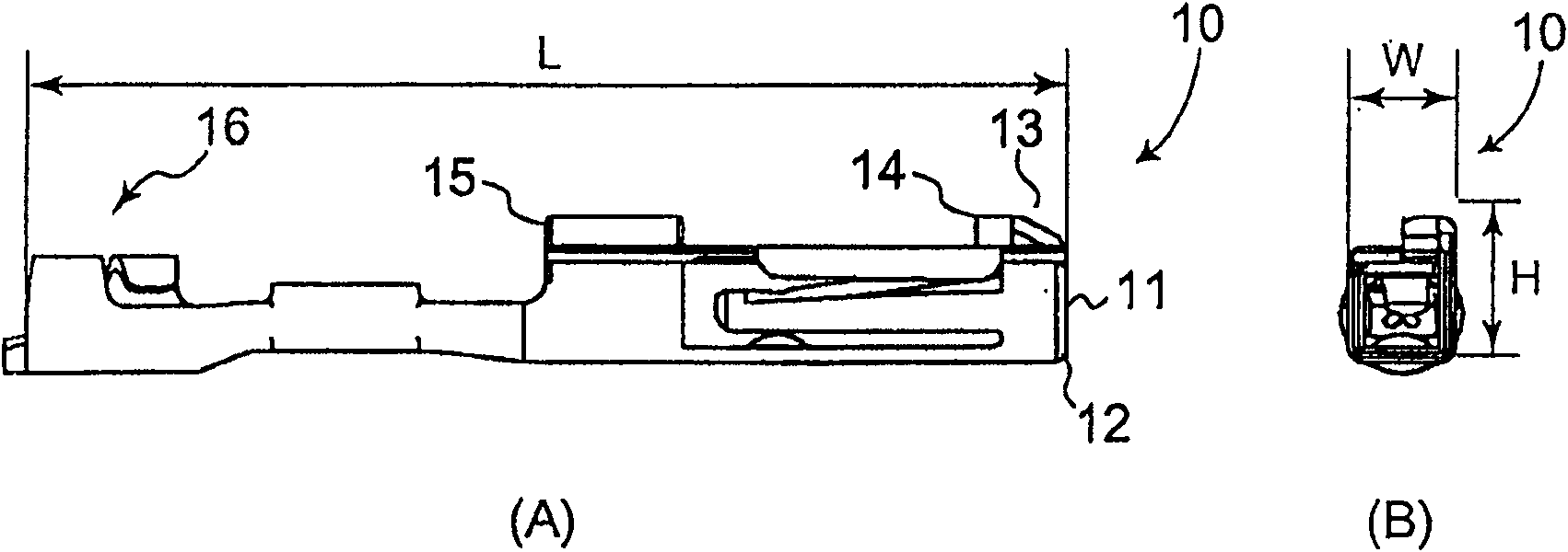
[0038] figure 1 A side view (A) and a front view (B) of contacts constituting the electrical connector according to the first embodiment of the present invention are shown.

[0039] Contact 10 is a female contact intended to receive a male contact (not shown) inserted from end 11 thereof. Near the other end of the contact 10 is provided a wire fitting portion 16 to which the end of the wire is connected.

[0040] The contact 10 has an edge 12 provided on one side of the end 11 to abut against a blocking structure (described below) in the housing when the contact is inserted backwards. The contact 10 also has a bevel 13 (which corresponds to the second bevel in the present invention) on the side opposite to the side where the edge 12 is located, and a first engagement section 14 and a second engagement section 15 for use in Prevents the contacts from slipping out of the hous...


PUM


Abstract

The present invention provides an electrical connector having contacts connected to electrical wires and a housing with sockets accommodating the contacts. The housing includes a blocking structure and a slope provided on the socket, so that the reversely inserted contact must butt against the blocking structure, thereby preventing further insertion of the contact. When the contact is correctly inserted into the socket, since the contact has an edge and a slope, the edge is guided by the slope of the housing, and the slope of the contact avoids abutting with the blocking structure and is guided by the blocking structure, so that the contact can be inserted smoothly. head.

Description

technical field [0001] The present invention relates to an electrical connector having contacts connected to electric wires and a housing with sockets (cavities) accommodating the contacts. Background technique [0002] Conventionally, there is known a technique for assembling an electrical connector by inserting contacts into sockets (cavities) provided in a housing. [0003] In the electrical connectors described above, although there is little problem with the case of round contacts, there is a possibility that square contacts are inserted into the housing in the wrong direction, resulting in failure of the connector engagement. In order to avoid such mis-insertions, especially counter-insertions, measures have been taken. These measures typically have both the contacts and the housing have irregularities configured to only allow insertion of the contacts into the housing in one orientation. [0004] For example, Japanese Patent Laid-Open No. 10-144379 describes that th...

Claims


Application Information

Patent Timeline
Patent Type & Authority Patents(China)
IPC IPC(8): H01R13/46H01R43/16
CPCH01R13/4223
Inventor 酒卷一诚南方真人小林浩西田笃史
Owner TYCO ELECTRONICS JAPAN GK
Features
  • R&D
  • Intellectual Property
  • Life Sciences
  • Materials
  • Tech Scout
  • Unparalleled Data Quality
  • Higher Quality Content
  • 60% Fewer Hallucinations
Learn More