Printing circuit board and method for testing anisotropic conducting membrance

A technology of anisotropic conductive film and printed circuit board, which is applied in the direction of printed circuit, measuring device, optical test defect/defect, etc. connected with non-printed electrical components, which can solve the problem that the detection of anisotropic conductive adhesive cannot be correctly judged, etc. question

Inactive Publication Date: 2007-08-22
AU OPTRONICS CORP
View PDF0 Cites 5 Cited by
  • Summary
  • Abstract
  • Description
  • Claims
  • Application Information

AI Technical Summary

Problems solved by technology

[0008] In order to solve the above problems, the present invention provides a printed circuit board and a method for detecting the anisotropic conductive film on it, so as to solve the problem that the detection of the anisotropic conductive adhesive cannot be correctly judged due to the difference in the manufacturing process disclosed in the known technology. The problem

Method used


Image

  • Printing circuit board and method for testing anisotropic conducting membrance
  • Printing circuit board and method for testing anisotropic conducting membrance
  • Printing circuit board and method for testing anisotropic conducting membrance

Examples


Embodiment Construction

[0017] Specific embodiments are given below to describe the content of the present invention in detail, and the accompanying drawings are used as auxiliary descriptions.

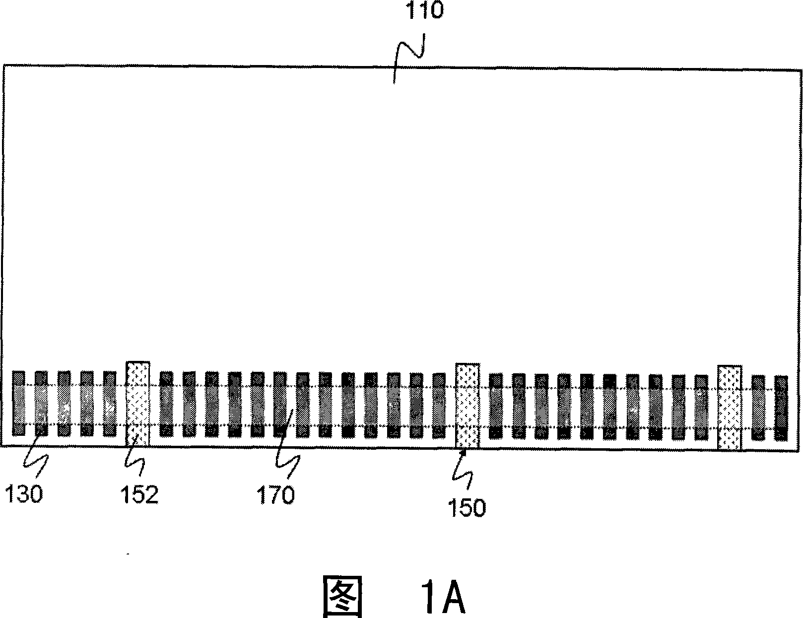
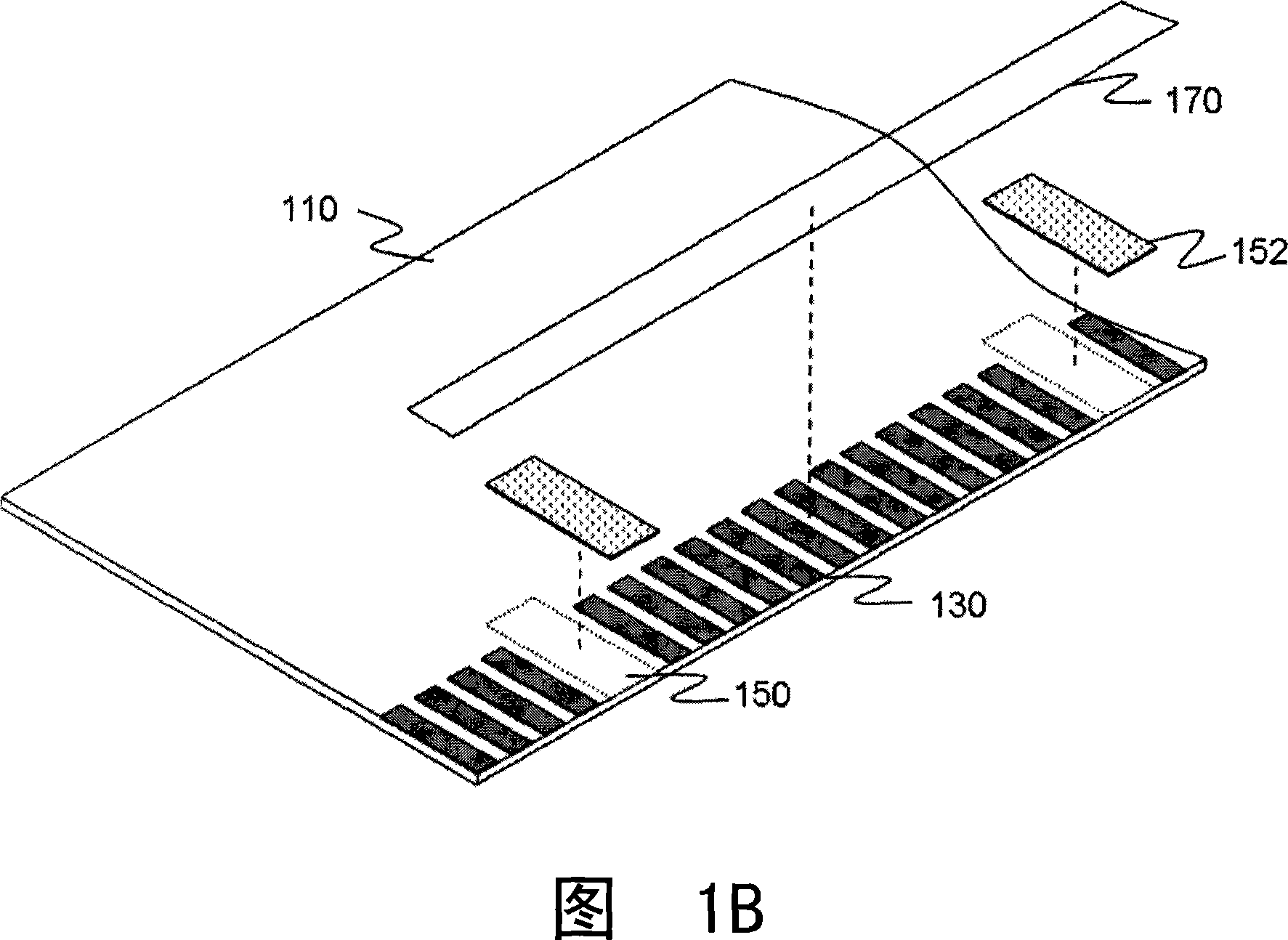
[0018] FIGS. 1A and 1B are schematic diagrams of a printed circuit board of the present invention. The printed circuit board includes: a substrate 110 , a conductive lead 130 , a detection area 150 and a pigment coating 152 .

[0019] The conductive terminals 130 are arranged in a row on the substrate 110 , and one or more detection regions 150 are disposed between the conductive terminals 130 , and the detection regions 150 are covered with a pigment coating 152 .

[0020] Among them, the pigment coating 152 is preferably a paint with stable color; more precisely, the pigment coating 152 is not easily affected by environmental conditions (eg, temperature, humidity, etc.). In a preferred embodiment, the pigment coating 152 is resistant to chemical solvents, especially commonly used chemical solvents (eg alco...


PUM


Abstract

A printed circuit board is prepared as arranging conductive terminals on base plate in column mode and setting detection region between said conductive terminals and covering dyestuff coat on said detection region.

Description

technical field [0001] The invention relates to a printed circuit board and a detection method thereof, in particular to a printed circuit board and a method for detecting an anisotropic conductive film thereon. Background technique [0002] The printed circuit board (PCB) is the main support body for the installation and insertion of electronic components, and it provides an interconnection transmission platform so that the functions of various components can be brought into play. [0003] During the manufacturing process of the display module, anisotropic conductive film (ACF) is usually used to electrically connect two parts. [0004] In the current liquid crystal panel manufacturing process, usually after the glass substrate is manufactured, the anisotropic conductive adhesive is first attached to the conductive terminal (1ead) on the edge of the glass substrate, and then the attached anisotropic conductive adhesive is used by a heating device. heating, and then tempora...

Claims


Application Information

Patent Timeline
IPC IPC(8): H05K1/18G01N21/956G01N21/95
Inventor 鲁柏树
Owner AU OPTRONICS CORP
Why Eureka
Try Eureka