Braking apparatus for vehicle

A technology of braking device and control device, applied in the direction of braking transmission, brake, vehicle components, etc., can solve the problems of delayed start of controlled hydraulic braking force, inability to maintain deceleration, uncomfortable brake pedal, etc.

Active Publication Date: 2007-10-10
ADVICS CO LTD
View PDF2 Cites 47 Cited by
  • Summary
  • Abstract
  • Description
  • Claims
  • Application Information

AI Technical Summary

Problems solved by technology

Correspondingly, the driver of the vehicle may experience an uncomfortable feeling - the brake pedal is suddenly depressed without further operation
[0009] Furthermore, in the case of replacing the regenerative braking force with the controlled hydraulic braking fo...

Method used


Image

  • Braking apparatus for vehicle
  • Braking apparatus for vehicle
  • Braking apparatus for vehicle

Examples


Embodiment Construction

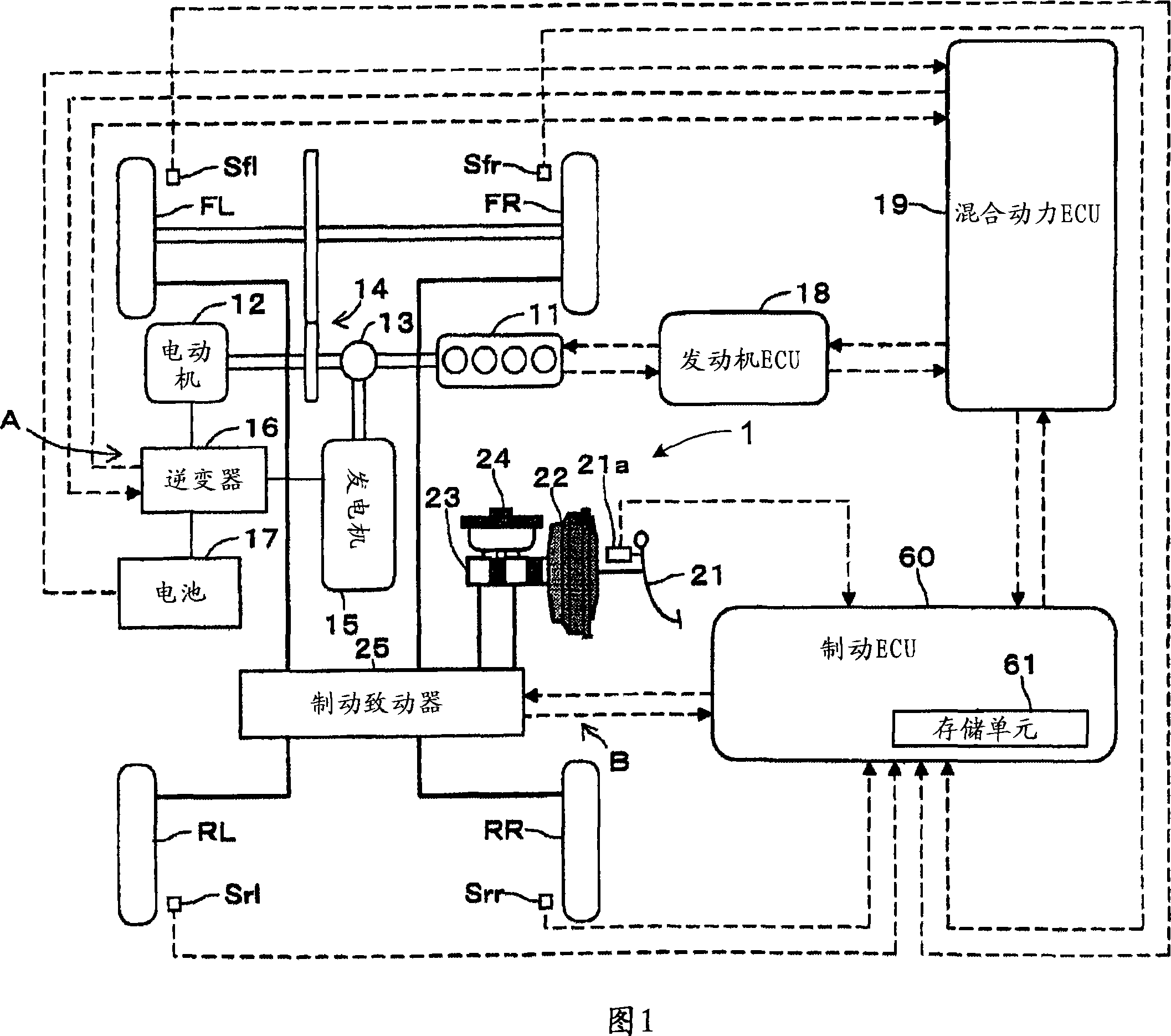
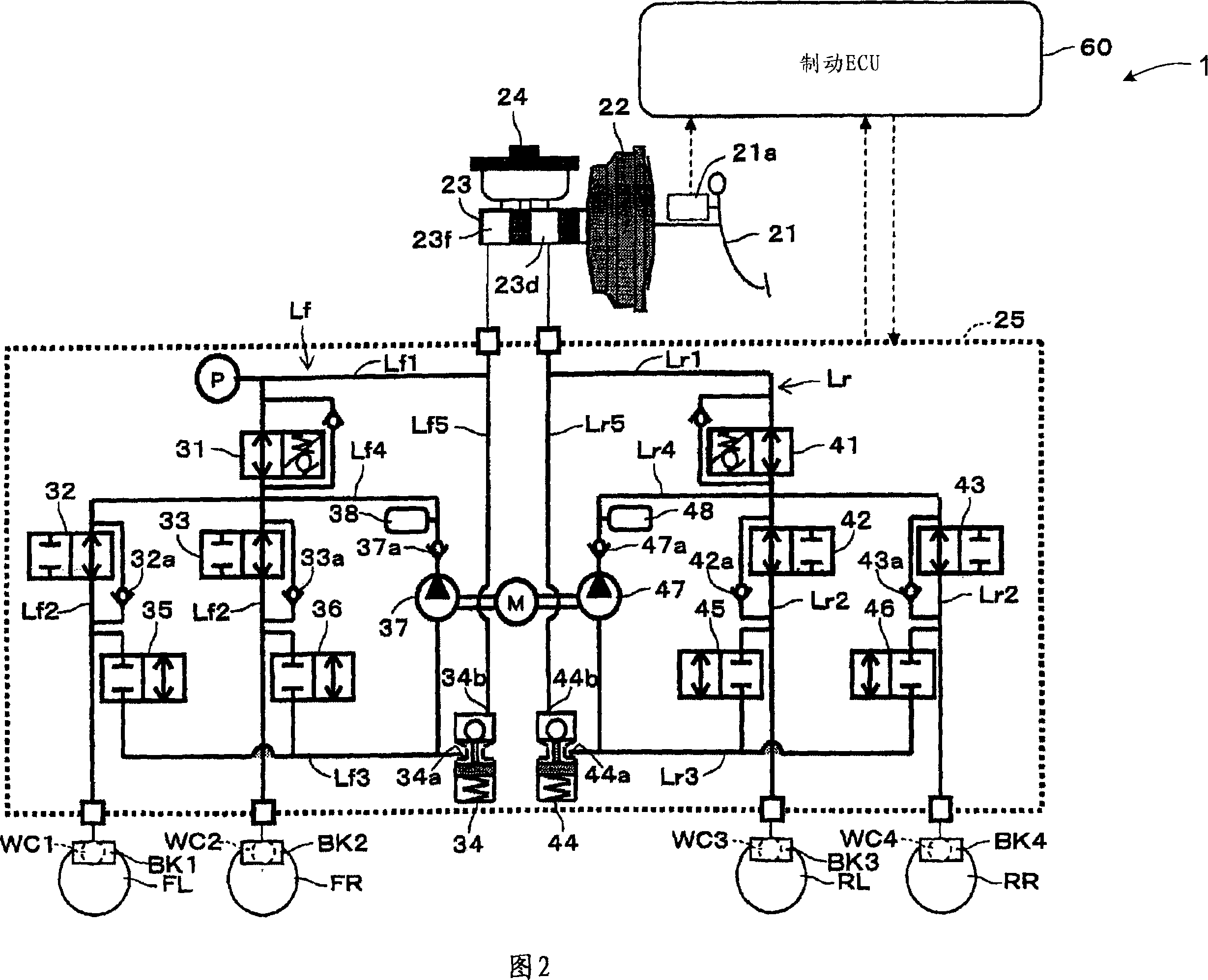
[0044] A brake device 1 for a vehicle according to a first embodiment of the present invention used in a hybrid vehicle will be explained with reference to the drawings. FIG. 1 is a schematic diagram showing the structure of a hybrid vehicle. FIG. 2 is a schematic diagram showing the structure of a hydraulic brake device of a hybrid vehicle. In a hybrid vehicle, drive wheels, ie, for example, a left front wheel FL and a right front wheel FR, are driven by the hybrid system shown in FIG. 1 . The hybrid system is a powertrain that uses two power sources, namely, the engine 11 and the electric motor 12 in combination. According to the invention, a parallel hybrid system is used in which both the engine 11 and the electric motor 12 directly drive the wheels. In addition to parallel hybrid systems, there are also known series hybrid systems in which an electric motor drives wheels and an engine is used as an electric power supply source for the electric motor.

[0045] A hybrid ...


PUM


Abstract

A braking apparatus for a vehicle includes a hydraulic brake apparatus generating a basic hydraulic pressure so that a basic hydraulic braking force is generated at wheels, the hydraulic brake apparatus generating a controlled hydraulic pressure so that a controlled hydraulic braking force is generated at the wheels, a regenerative brake apparatus causing a regenerative braking force to be generated at any of the wheels, and braking force replacement controlling means for gradually replacing the regenerative braking force with the controlled hydraulic braking force while braking during which at least the regenerative braking force is applied for a purpose of achieving a braking force replacement control to ensure a total braking force required for the wheels by decreasing the regenerativebraking force at a gradient within a predetermined range and by increasing the controlled hydraulic braking force in response to the decrease of the regenerative braking force.

Description

technical field [0001] The present invention generally relates to a braking device for a vehicle. More particularly, the present invention relates to a braking device for a vehicle that obtains a braking force as a sum of a hydraulic braking force generated by a hydraulic braking device and a regenerative braking force generated by a regenerative braking device in response to a brake operation state. The total braking force applied to the wheels. Background technique [0002] A known brake device for a vehicle disclosed, for example, in JP2006-21745A includes a hydraulic brake device and a regenerative brake device. The hydraulic brake device generates base hydraulic pressure from a master cylinder in response to a brake operation, and applies the generated base hydraulic pressure to wheel cylinders provided at respective wheels connected to the master cylinder through a fluid passage provided with a hydraulic control valve, so that at Hydraulic braking force is generated ...

Claims


Application Information

Patent Timeline
IPC IPC(8): B60T13/20
CPCY02T10/6221
Inventor 牧一哉小久保浩一内藤政行
Owner ADVICS CO LTD
Why Eureka
Try Eureka