
Electromagnetic door lock

An electromagnetic door lock and electromagnet technology, which is applied in building locks, locks controlled by non-mechanical transmission, buildings, etc., can solve the problems of long locking/unlocking time, insufficient safety, laborious operation, etc.

Inactive Publication Date: 2011-07-06
HANGZHOU KAMBAYASHI ELECTRONICS
View PDF3 Cites 0 Cited by
  • Summary
  • Abstract
  • Description
  • Claims
  • Application Information

AI Technical Summary

Problems solved by technology

[0017] In order to solve the existing problems of the washing machine door locks such as long locking / unlocking time, laborious operation, or insufficient security, the electromagnetic door lock of the present invention is proposed, which is convenient for locking / unlocking , fast, and effortless, the washing machine can also keep the door locked when abnormal power failure occurs during washing, preventing the washing and water from flowing out; the preferred mode of the present invention can provide a door closing signal and a locking signal for washing program control of the washing machine; The invention can also realize convenient left hand closing and opening and closing door lock or right hand closing and opening and closing door lock according to user's habit needs

Method used


Image

  • Electromagnetic door lock
  • Electromagnetic door lock
  • Electromagnetic door lock

Examples


Embodiment 1

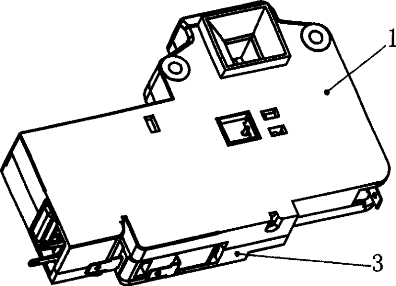
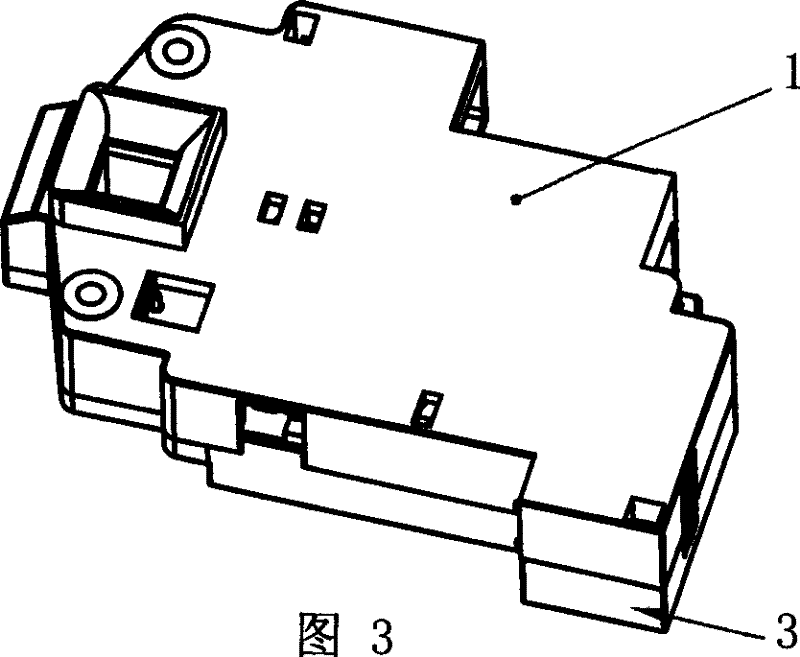
[0046] Electromagnetic door lock, see figure 2 , Figure 4 , Figure 17 , with a base body 1 and its connected upper cover 3, the base body 1 is provided with a hook hole 100 for the door hook to be inserted when the door is closed, and an electromagnet 11 is provided with an iron core 17 connected to its front end, and a sliding lock is arranged inside the base body 1 The upper end of the buckle 2 has a locking hole 200 corresponding to the hook hole 100 on the base. The sliding lock is provided with a spring slot 201 and a protrusion 202 used for locking and holding. In the spring slot 201 of the lock catch, spring I21 and spring II22 are arranged in the spring slot 201 to be respectively located at two top spring protrusion pins 102 in the spring slot, and an operation panel 4 is arranged in the base body to connect with the iron core 17, and the operation panel A return spring 20 is provided between the protrusion 103 on the base body, a positioning / resetting groove pla...

Embodiment 2

[0049] This example electromagnetic door lock, see Figure 5 , based on Embodiment 1, the electromagnetic door lock is provided with a micro switch 8 in the base body, a button 801 is provided on one side, and a protrusion 205 and a protrusion 206 are connected on the sliding lock. Corresponding to the button 801 of the micro switch; other constructions are the same as those in Embodiment 1.

[0050] When the door hook is hooked downward after the door is closed, the sliding lock 2 moves down, the spring 21 is compressed, and the protrusion 205 presses the button 801 to conduct the micro switch 8 to generate and output the door closing signal; when the door hook is disengaged, the sliding lock Buckle 2 resets under the action of spring 21, and projection 205 leaves button 801, and microswitch 8 is disconnected, and the door closing signal is released. If the door hook is hooked upwards, the sliding latch moves upwards, the spring 22 is compressed, and the projection 206 press...

Embodiment 3

[0052] See Image 6 , The electromagnetic door lock is based on the second embodiment, the base body is provided with a micro switch 9 with a button 901 on one side, and the operation panel 4 has a protrusion 402 corresponding to the button 901; other structures are the same as those of the second example.

[0053] When the lock is held, the protrusion 402 on the operating panel presses the button 901 to make the micro switch 9 conduct, and a lock signal is generated and output; when the lock is released and held, the unlock signal is output.


PUM


Abstract

A rapid electromechanical door lock capable of convenient in using comprises a base body (1) which is provided with a hook-hole (100) for the door-hook inserting in as closing the door, and the base body is also provided with an electromagnet (11) whose front end is connected with an iron core (17), and a sliding lock (2) is arranged in the base body and is provided with a locked hole (200) on the upper end relative to the hook-hole (100) on the base body, wherein the sliding lock is also provided with a spring equipped groove (201) and a boss (202), and the base body is connected with a top spring raised bolt (102) which is positioned in the spring equipped groove, while a spring is arranged in the spring equipped groove (201) and is positioned between the end wall of the spring equippedgroove and the top spring raised bolt. An operation board (4) is arranged in the base body and is connected with the iron core (17), and a resetting spring (20) is arranged between the operation board and a boss (103) equipped on the base body, and the middle portion of the operation board (4) is provided with a location / resetting groove table which is relative to a location needle (25) connectedwith the base body, while the front end of the operation board is connected with a boss (403) which is relative to the boss of the sliding lock. The invention is applicable to the laundry machine door lock.

Description

technical field [0001] The invention relates to a locking and unlocking device for a door lock, in particular to a locking and unlocking device for a drum washing machine door lock. Background technique [0002] The locking and unlocking device of the drum type washing machine door currently produced and sold, that is, the door lock switch was originally designed from European countries. The simple overall diagram of this washing machine and its door lock is as follows: figure 1 As shown, there is a drum b inside the body a, and the drum mouth e is located on the front of the body for putting in and taking out laundry. The front of the base body is provided with a door g for opening and closing the drum mouth, and the door g is provided with a door hook f , there is an opening d on the front vertical wall of the body, and the door hook f is locked in the opening d of the body. [0003] The opening of the door lock device c fits with the opening of the door body. After the ...

Claims


Application Information

Patent Timeline
Patent Type & Authority Patents(China)
IPC IPC(8): E05B47/02
Inventor 徐伟王华
Owner HANGZHOU KAMBAYASHI ELECTRONICS
Learn More