Electromagnetic door lock
A technology for electromagnetic door locks and sliding locks, which can be used in construction locks, non-mechanical transmission-operated locks, construction, etc., and can solve the problems of long locking/unlocking time, laborious operation, and insufficient security.
- Summary
- Abstract
- Description
- Claims
- Application Information
AI Technical Summary
Problems solved by technology
Method used
Image
Examples
Embodiment 1
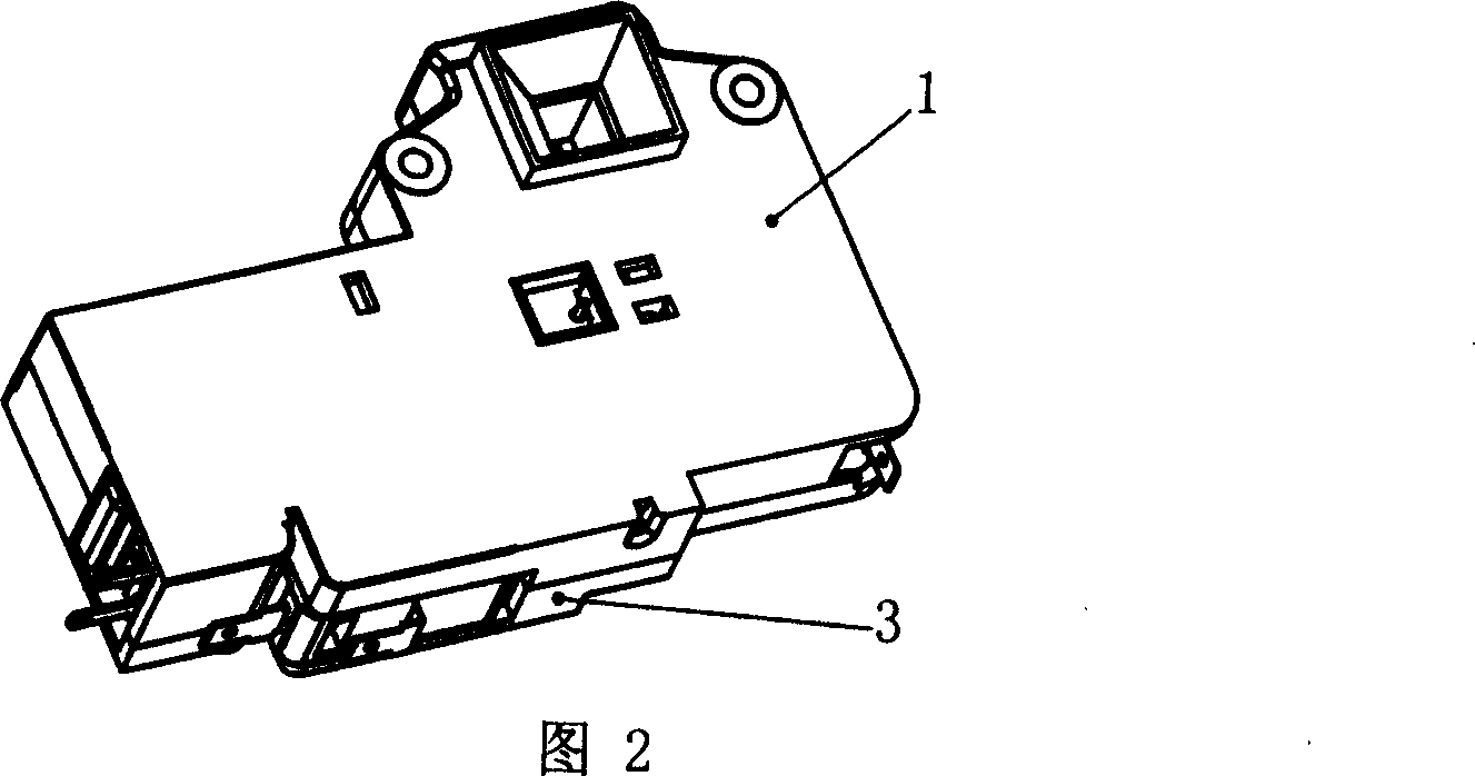
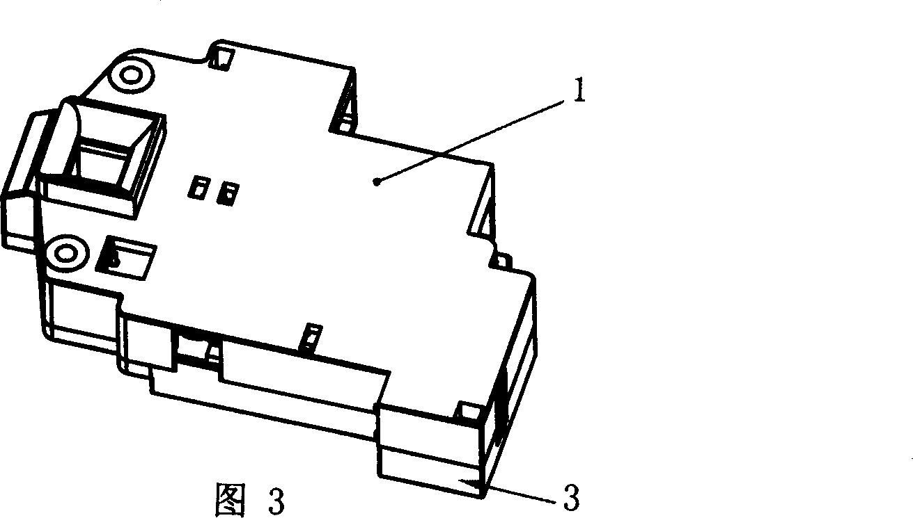
[0046] Electromagnetic door lock, referring to Fig. 2, Fig. 4, Fig. 17, has base body 1 and its connected loam cake 3, base body 1 is provided with the hook hole 100 that the door hook is inserted when closing the door, and is provided with electromagnet 11 its front end Connected with iron core 17, the base body 1 is provided with a sliding lock 2, the upper end of which has a locking hole 200 corresponding to the hook hole 100 on the base, and the sliding lock is provided with a spring slot 201 and a protrusion for locking and holding 202, the top spring protruding pin 102 is connected to the base body and is located in the spring groove 201 of the sliding lock. The spring groove 201 is provided with spring I 21 and spring II22 respectively located in the spring groove. The operating panel 4 is connected with the iron core 17, the return spring 20 is provided between the operating panel and the protrusion 103 on the base body, the middle part of the operating panel 4 is provi...
Embodiment 2
[0049] The electromagnetic door lock of this example is shown in Figure 5. Based on the first embodiment, the electromagnetic door lock is provided with a micro switch 8 in the base body, a button 801 is provided on one side, and a protrusion 205 and a protrusion 206 are connected on the sliding lock. The notch with two sloped walls in between corresponds to the button 801 of the micro switch; the other structures are the same as in Embodiment 1.
[0050] When the door hook is hooked downward after the door is closed, the sliding lock 2 moves down, the spring 21 is compressed, and the protrusion 205 presses the button 801 to conduct the micro switch 8 to generate and output the door closing signal; when the door hook is disengaged, the sliding lock Buckle 2 resets under the action of spring 21, and projection 205 leaves button 801, and microswitch 8 is disconnected, and the door closing signal is released. If the door hook is hooked upwards, the sliding latch moves upwards, th...
Embodiment 3
[0052] See Fig. 6, the electromagnetic door lock is based on the second embodiment, the base body is provided with a micro switch 9 with a button 901 on one side, and the operation panel 4 has a protrusion 402 corresponding to the button 901; other structures are the same as in the second example.
[0053] When the lock is held, the protrusion 402 on the operating panel presses the button 901 to make the micro switch 9 conduct, and a lock signal is generated and output; when the lock is released and held, the unlock signal is output.
PUM
 Abstract
Description
Claims
Application Information
 - R&D
- Intellectual Property
- Life Sciences
- Materials
- Tech Scout
- Unparalleled Data Quality
- Higher Quality Content
- 60% Fewer Hallucinations
Browse by: Latest US Patents, China's latest patents, Technical Efficacy Thesaurus, Application Domain, Technology Topic, Popular Technical Reports.
© 2025 PatSnap. All rights reserved.Legal|Privacy policy|Modern Slavery Act Transparency Statement|Sitemap|About US| Contact US: help@patsnap.com


