Global timing mark synchronization method and system of switching network of multiple planes

A switching network, multi-plane technology, applied in the field of communication, can solve problems such as different structures and complex structures

Active Publication Date: 2007-12-26
HUAWEI TECH CO LTD
View PDF0 Cites 6 Cited by
  • Summary
  • Abstract
  • Description
  • Claims
  • Application Information

AI Technical Summary

Problems solved by technology

[0008] However, the structure of the multi-plane switching network is different from that of the single-plane switching network, and its structure is more complicated than that of

Method used


Image

  • Global timing mark synchronization method and system of switching network of multiple planes
  • Global timing mark synchronization method and system of switching network of multiple planes
  • Global timing mark synchronization method and system of switching network of multiple planes

Examples


Embodiment Construction

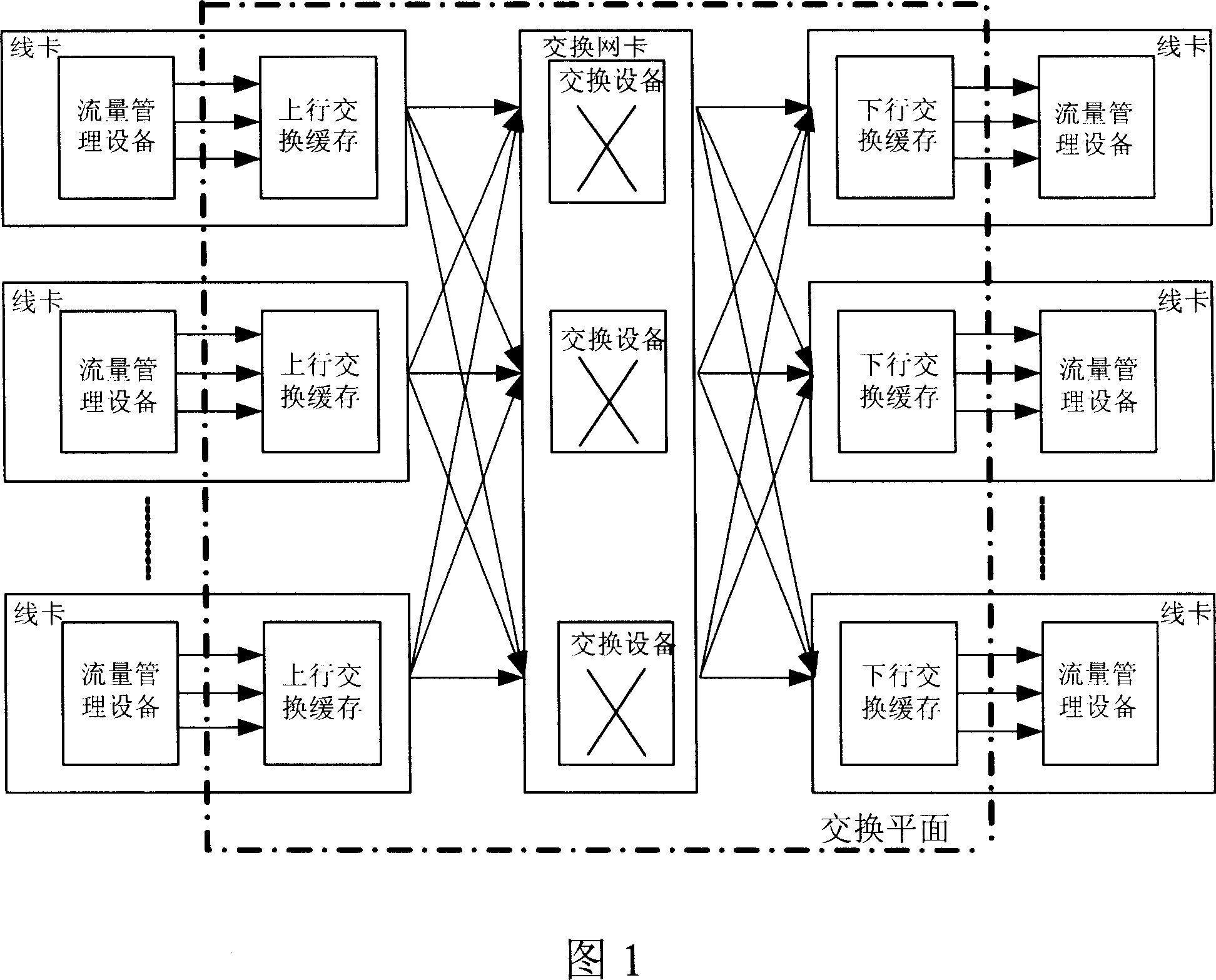
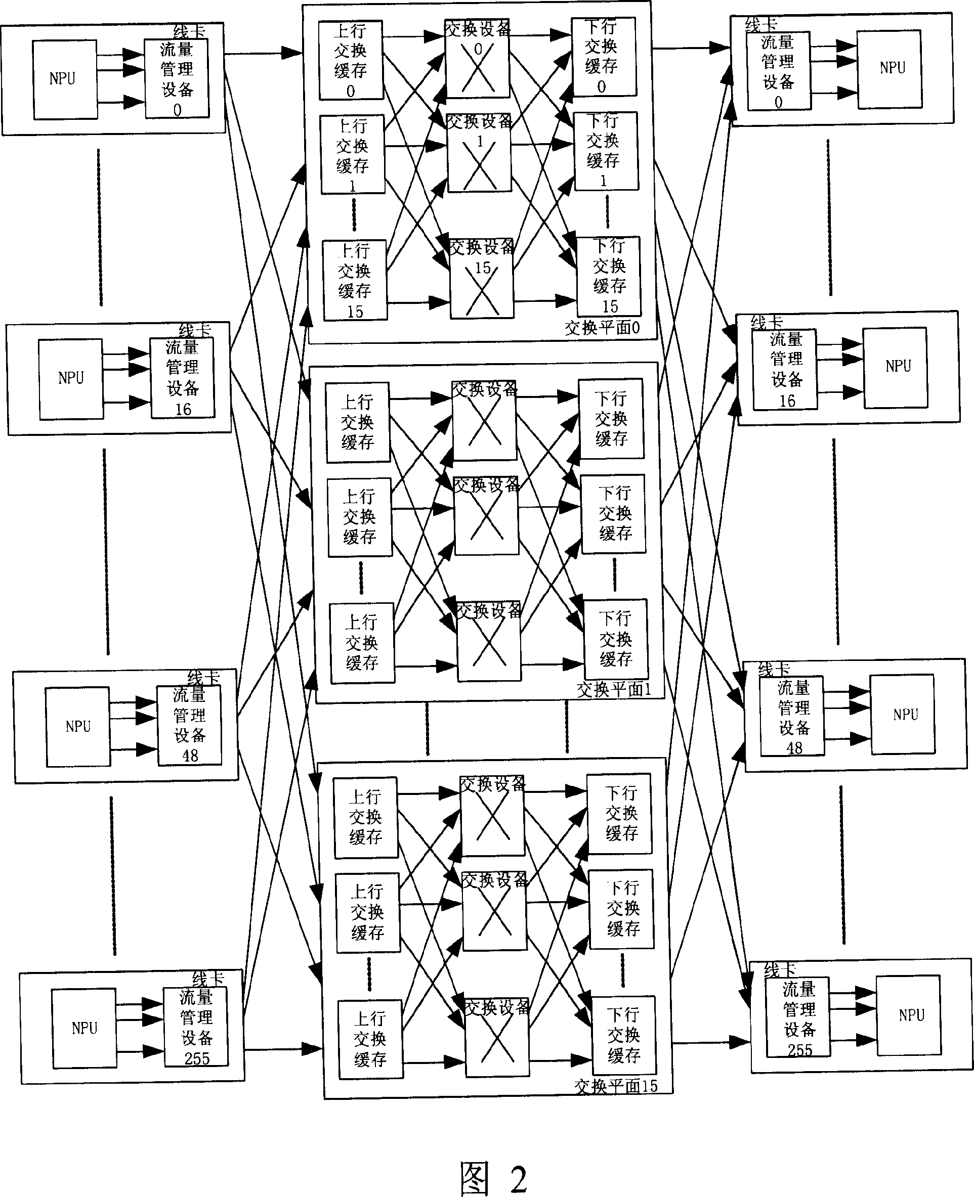
[0030] In the embodiment of the present invention, the global time stamp distribution device is determined by constructing the network topology structure of the multi-plane switching network according to the link state information of the multi-plane switching network, and the global time stamp distribution device distributes a unique global time stamp The traffic management equipment marked to the multi-plane switching network system realizes the global time stamp synchronization of the multi-plane switching network.

[0031] The technical solutions of the embodiments of the present invention will be further described below in conjunction with the accompanying drawings.

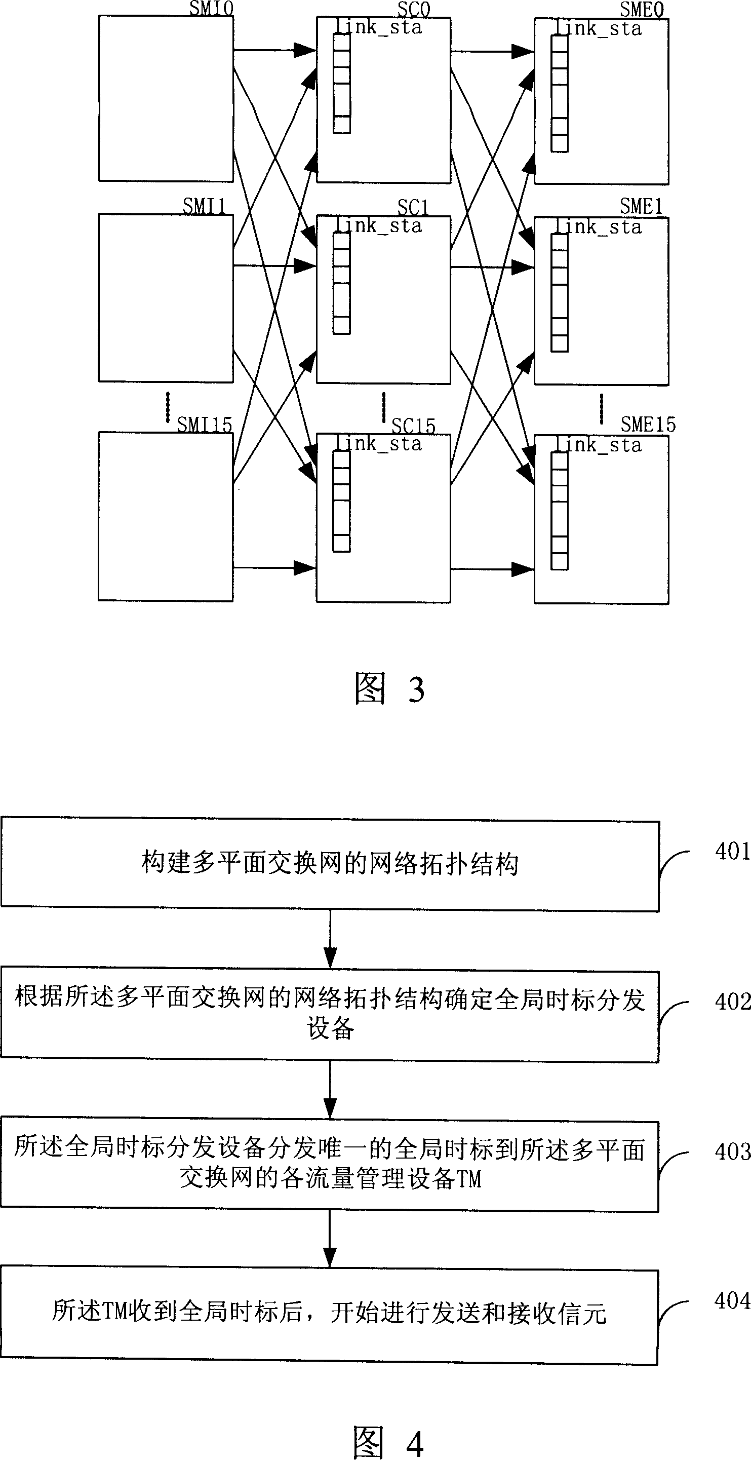
[0032] As shown in FIG. 4, a global time scale synchronization method for a multi-plane switching network provided by an embodiment of the present invention includes the following steps:

[0033] S401. Construct a network topology structure of the multi-plane switching network according to link state informat...


PUM


Abstract

The method comprises: according to the link state information about multi-plane switching network, constructing the network topology structure of the multi-plane switch network; said network topology structure of the multi-plane switch network is used for confirming the global time scale dispensing device; said global time scale dispensing device is used to dispense a unique global time scale to each traffic manager (TM) in said multi-plane switching network; after receiving said global time scale, each TM sends and receives cells. Said system thereof comprises: topology constructing unit, global time scale dispense device confirming unit, global time scale dispensing unit, and at least one TM.

Description

technical field [0001] The invention relates to the technical field of communication, in particular to a global time scale synchronization method and system for a multi-plane switching network. Background technique [0002] The switching network is the core of the router, which is used to complete the exchange of data packets or cells between multiple ports, that is, to switch the data packets or cells arriving at the input port to the corresponding output port. According to the number of switching planes, the switching network can be divided into a single-plane switching network and a multi-plane switching network. [0003] Figure 1 is a schematic structural diagram of a typical single-plane switching network. The switching network includes a switching cache (SM) on a line card and a switching device (SC) on a switching network card, wherein the switching cache includes an uplink switching cache (SMI) With the downlink exchange cache (SME), the SMI and the SME can be logic...

Claims


Application Information

Patent Timeline
IPC IPC(8): H04L12/04H04Q3/00H04L12/28
Inventor 罗焰斌
Owner HUAWEI TECH CO LTD
Why Eureka
Try Eureka