Telescopic shaft
A telescopic shaft and shaft center technology, which is applied to the steering column and the steering control installed on the car, etc., can solve the problems of insufficient removal of looseness, excessive sliding resistance, etc., and achieve the effect of not reducing the pre-pressure
- Summary
- Abstract
- Description
- Claims
- Application Information
AI Technical Summary
Problems solved by technology
Method used
Image

Examples
Embodiment 1
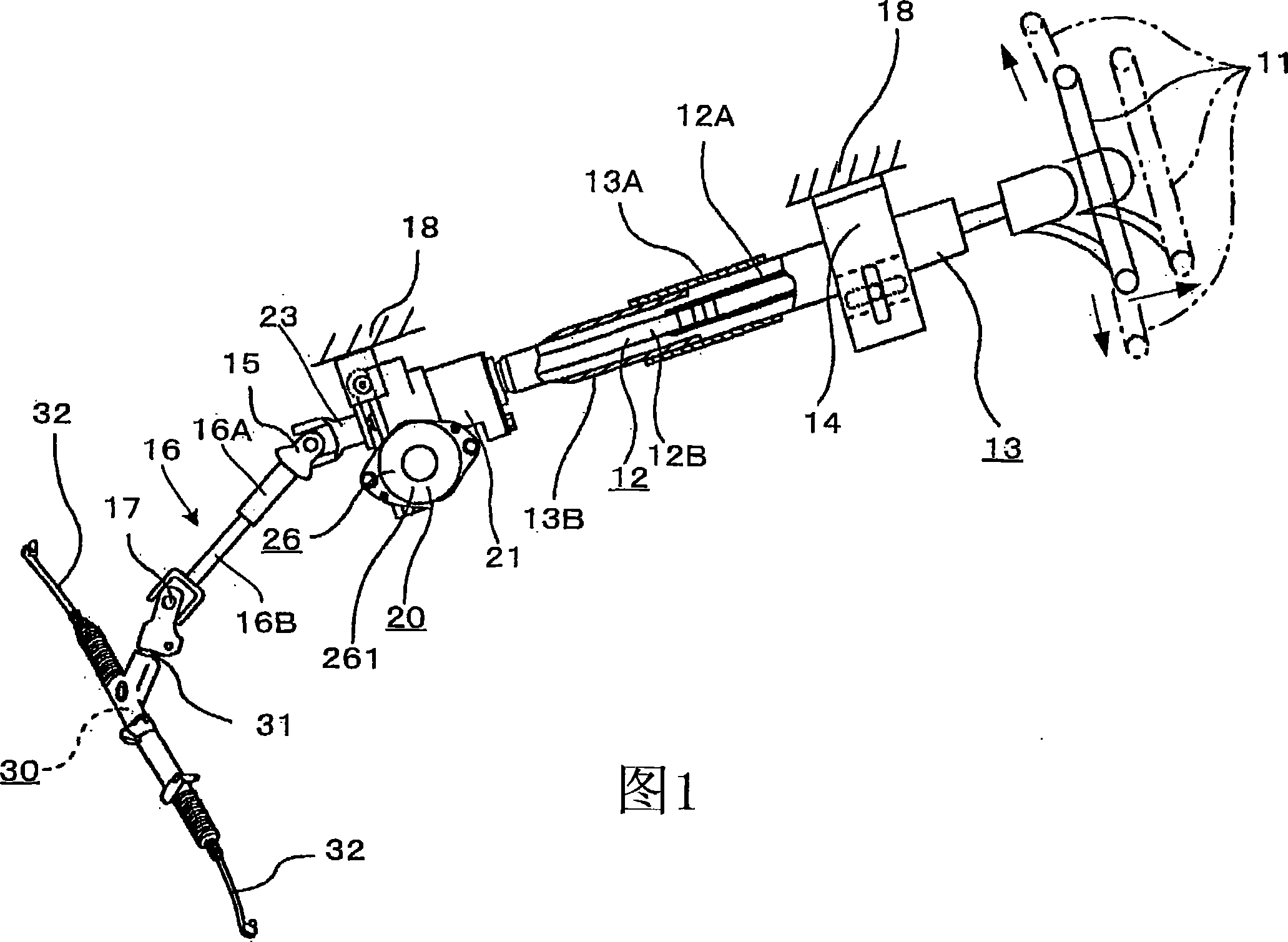
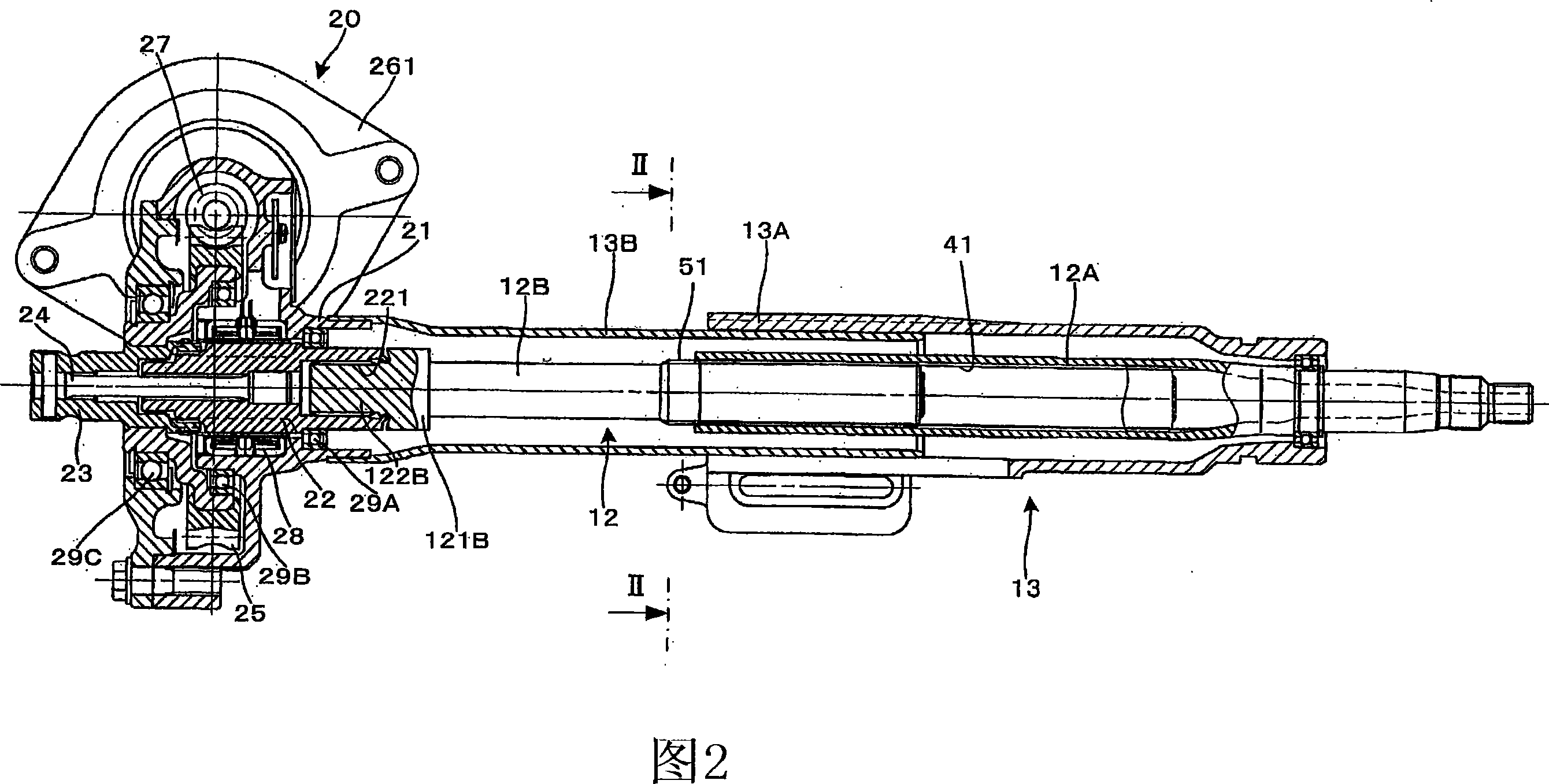
[0068] FIG. 1 is a partially cutaway front view showing the entire steering device according to Embodiment 1 of the present invention, and shows an embodiment applied to an electric power steering device having a steering assist unit. Fig. 2 is a longitudinal sectional view of the main part of Fig. 1 .
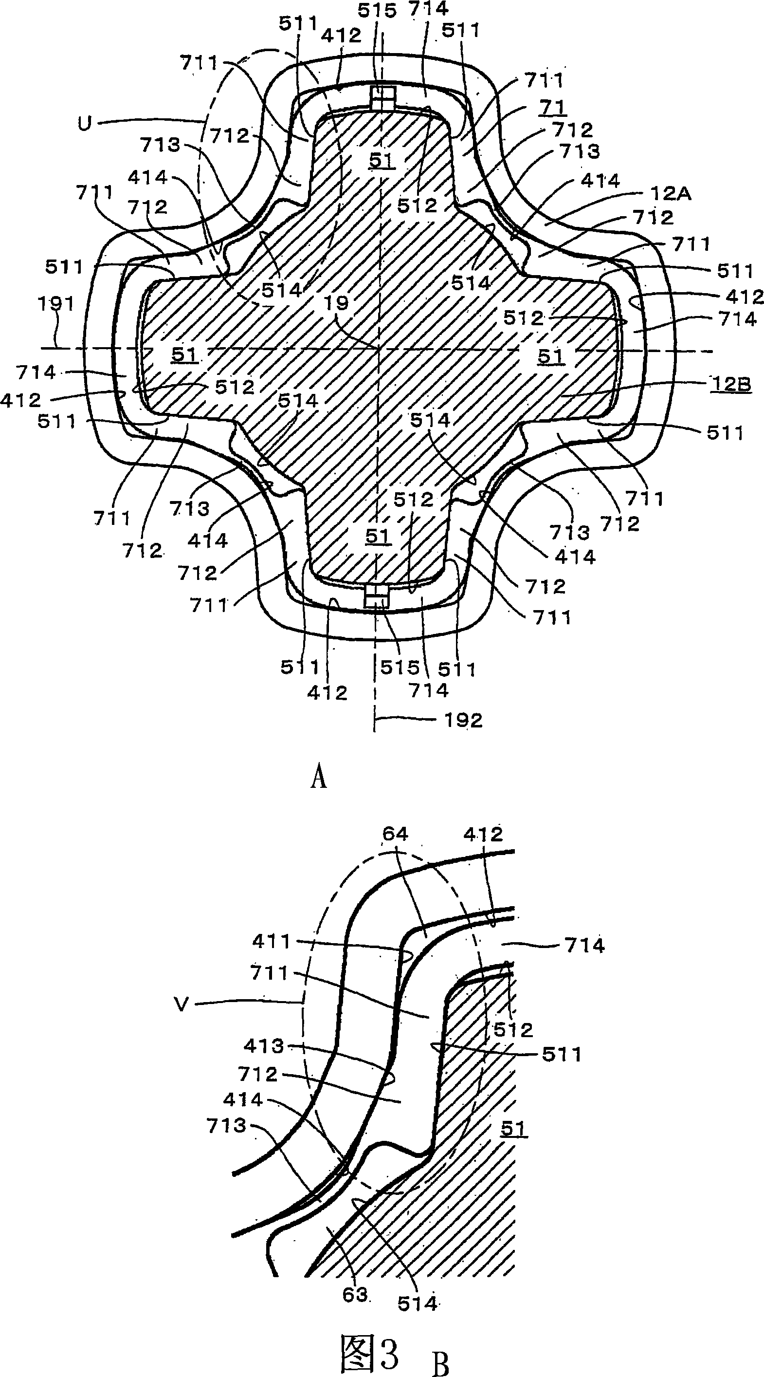
[0069] Fig. 3 shows the telescoping shaft of embodiment 1 of the present invention, and Fig. 3 (A) is II-II enlarged sectional view of Fig. 2, and Fig. 3 (B) is the U portion enlarged sectional view of Fig. 3 (A). Fig. 4 is an enlarged sectional view showing only the male shaft and the female shaft with the sleeve removed from Fig. 3(A). Fig. 5 is an enlarged cross-sectional view showing a state before a sleeve is attached to the male shaft and fitted onto the female shaft in Fig. 3(A).
[0070] Fig. 6 is an enlarged cross-sectional view of the V part of Fig. 3(B). Fig. 6(A) shows the state where no rotational torque is loaded between the male shaft and the female shaft, and ...
Embodiment 2
[0136] Next, Embodiment 2 of the present invention will be described. Fig. 10 shows the telescopic shaft according to the second embodiment of the present invention, the male shaft, the female shaft and the sleeve are taken as cross-sections, corresponding to the enlarged cross-sectional view of II-II in Fig. 2 . In the following description, only the structural parts and functions different from those of the first embodiment will be described, and redundant description will be omitted. In addition, the same structures as those of the above-mentioned first embodiment are described with the same reference numerals.
[0137] Embodiment 2 is a modified example of Embodiment 1. The force applying sleeve part and the connecting sleeve part are made in a wave shape, the connecting sleeve part is in contact with the outer peripheral part of the male shaft 12B, and the force applying sleeve part is in contact with the female shaft sleeve part. The inner peripheral portions of 12A are...
Embodiment 3
[0144] Next, Embodiment 3 of the present invention will be described. Fig. 11 shows the telescopic shaft according to the third embodiment of the present invention, the male shaft, the female shaft and the sleeve are taken as cross-sections, corresponding to the enlarged cross-sectional view of II-II in Fig. 2 . In the following description, only structural parts and functions different from those of the above-mentioned embodiments will be described, and repeated descriptions will be omitted. In addition, the same reference numerals are assigned to the same configurations as those of the above-mentioned embodiments and described.
[0145] Embodiment 3 is a modified example of Embodiment 1. The connecting sleeve part is in a wave shape, and the connecting sleeve part is in contact with the inner circumference of the female shaft 12A. There is always a gap in between.
[0146] That is, in Example 3, the shape of the urging sleeve part 713 is the same as that of Example 1, and ...
PUM
 Abstract
Description
Claims
Application Information
 - R&D
- Intellectual Property
- Life Sciences
- Materials
- Tech Scout
- Unparalleled Data Quality
- Higher Quality Content
- 60% Fewer Hallucinations
Browse by: Latest US Patents, China's latest patents, Technical Efficacy Thesaurus, Application Domain, Technology Topic, Popular Technical Reports.
© 2025 PatSnap. All rights reserved.Legal|Privacy policy|Modern Slavery Act Transparency Statement|Sitemap|About US| Contact US: help@patsnap.com