Ink container, recording head and recording device using same

a recording head and recording device technology, applied in printing and other directions, can solve the problems of insufficient color recording, inability to print, and inability to uniform fiber distribution, etc., to achieve stable ink supply, improve printing efficiency, and improve printing efficiency.

Inactive Publication Date: 2006-11-14
CANON KK
View PDF33 Cites 41 Cited by
  • Summary
  • Abstract
  • Description
  • Claims
  • Application Information

AI Technical Summary

Benefits of technology

[0025]With this structure, since the liquid retaining force of the first liquid retaining member is larger than that of the second liquid retaining member, the liquid in the liquid container tends to be retained more in the neighborhood of an external member to which the liquid is to be supplied, and therefore, the liquid in the liquid container is stabilized. In addition, by the first liquid retaining member extending substantially along the inner surface configuration of the portion having the liquid supply opening of the casing, the variation of the liquid flow within the second liquid retaining member, that is, the variation in the flow resistance in the second liquid retaining member (variation in the fiber density and the like) is less influential, so that liquid can be supplied stably even if the flow rate is large. Therefore, a stable ink supply is accomplished in a thin and flat type liquid container. In addition, since the liquid retaining force of the first liquid retaining member is larger than that of the second liquid retaining member, the amount of the remaining liquid after the liquid discharge is larger in the first liquid retaining member than in the second liquid retaining member. Particularly, in the case of the high speed liquid supply, the influence is relatively larger. When the first liquid retaining member is in the form of a thin sheet, the above-described effect can be provided, and the inside volume of the first liquid retaining member is decreased, thus decreasing the remaining amount of the liquid. With such a structure, a wasteful space can be eliminated in an ink container having a rectangular parallelopiped configuration, thus increasing the ink accommodation space, and permitting a consumption of the ink without waste even in the case of high speed recording. Thus, the present invention can provide an ink container, a first object using the ink container and-a recording device using the same, which can be suitably employed with a small size recording device and which has an improved ink supply speed into the ink jet recording head, an improved ink accommodation efficiency and an improved ink use efficiency.
[0026]According to a further aspect of the present invention, there is provided a ink jet recording head comprising a holder for detachably holding an ink container as described above and a recording head portion for receiving the ink from said ink container held in said holder and for ejecting ink droplets, and a ink jet recording apparatus comprising a carriage for detachably carrying such an ink jet recording head, wherein the ink droplets are ejected from said ink jet recording head onto a recording material to effect recording on the recording material.

Problems solved by technology

In the case that high speed recording is carried out using the recording head capable of such high speed recording with the conventional ink container, the color recording is not appropriately performed despite the fact that sufficient amount of the ink remains in the ink container in some cases.
In addition, particularly when the fiber absorbing material is used as the negative pressure generating member, the fibers are arranged with a desired distribution macroscopically, but the distribution state of the fibers are not uniform microscopically due to the variation in the gaps between the fibers and / or in the thickness of the fibers and / or due to the error in the manufacturing step.
When the ink supply speed is increased in an attempt to accomplish the high speed recording, the ink retained in the sparse fiber portion of the fiber absorbing material is consumed with high priority even to such an extent that before start of discharge of the ink retained in the dense fiber portion, the ink flow path is disconnected, with the result of stop of ink supply and therefore disabled printing operation.
Such a problem is newly found with further increase of the printing speed.
However, the ink container for use with a small size color printer, particularly, an integral type color ink container containing a plurality of color inks (not more than 10 ml for each color), suffers from a small space which can be given in the recording device.
This results in the fiber density in the ink absorbing material, which means a reduced ink retaining space, and therefore, the retainable amount of the ink decreases.
However, the distance from the ink retained at a position right above the ink supply port in the ink absorbing material and the ink supply port is short, and therefore, such ink exists adjacent the bottom surface of the ink container away from the ink supply port in the horizontal direction, so that such ink can be more easily discharged than the ink which is not easily influenced by the gravity.
As a result, in the case of high speed recording, the ink use efficiency tends to decrease because of the large difference in the easiness of ink supply due to the difference in the distance from the ink supply port.
In the case of the ink container for use with the small size color printer, the compossibility of the improvement in the ink supply speed into the ink jet recording head, the improvement in the ink accommodation efficiency and the ink use efficiency, are difficult, because of the constraint in the size.

Method used


Image

  • Ink container, recording head and recording device using same
  • Ink container, recording head and recording device using same
  • Ink container, recording head and recording device using same

Examples


first embodiment

(First Embodiment)

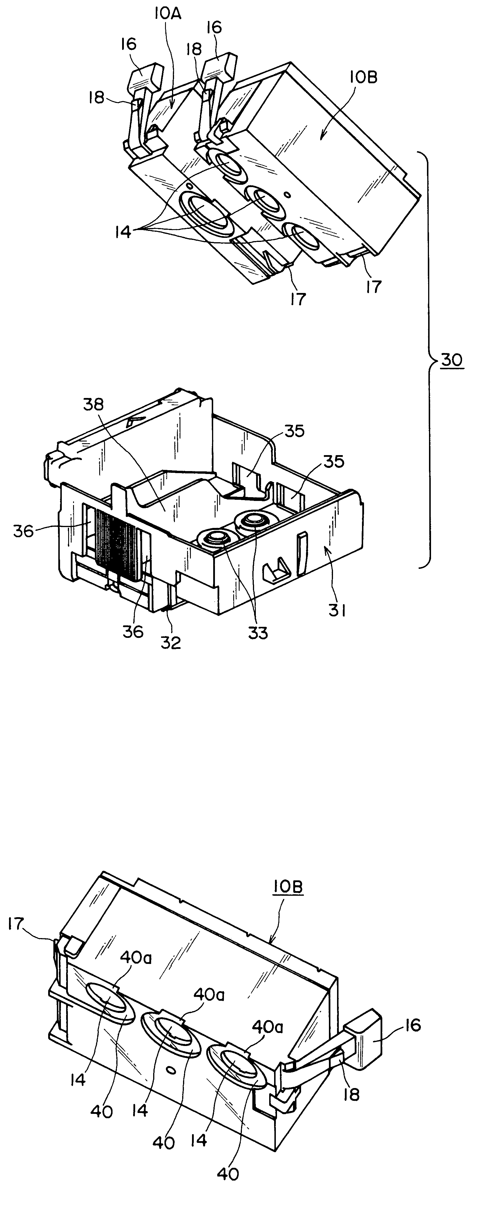
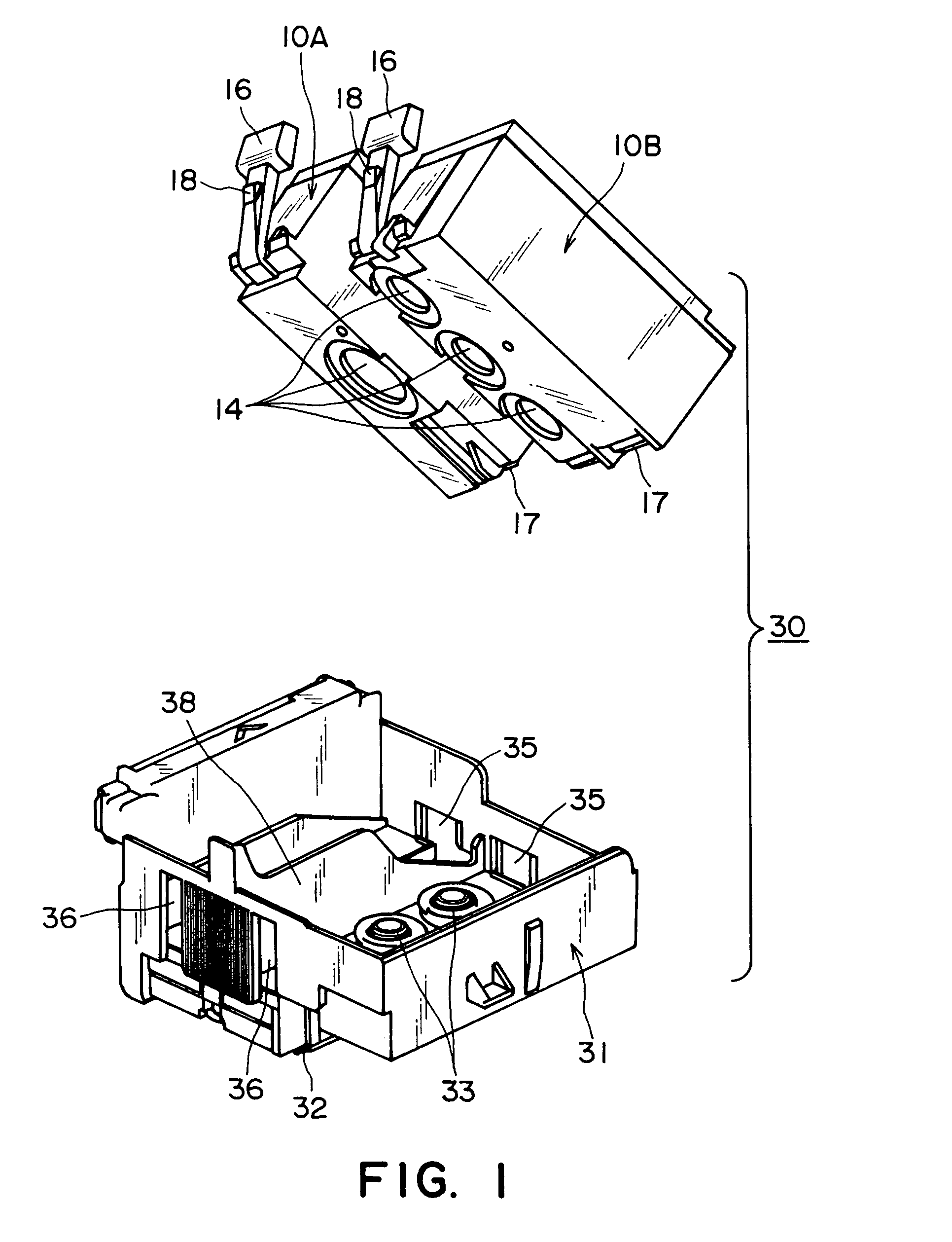
[0075]First example will be described referring to the drawings. FIG. 8 illustrates an ink jet cartridge 130 comprising an ink container 110 (liquid container) and a holder 131 to which the ink container 110 is mountable. FIG. 8 is a partly broken perspective view, in which the holder 131 and the ink container 110 are separated for better understanding.

[0076]As shown in FIG. 8, the ink jet cartridge 130 includes a holder 131 having an-integral ink jet head 132 for ejecting the ink, and an ink container 110 detachably mountable to the holder 131. The ink container 110 accommodates the ink which is liquid to be supplied to the ink jet head 132.

[0077]The ink jet head 132, in use, is disposed on the bottom portion of the holder 131 and is provided with a group (unshown) of ejection outlets through which the ink supplied from the ink container 110 is ejected out. At the connecting portion between the holder 131 and the ink container 110, an ink receiving tube (outer mem...

second embodiment

(Second Embodiment)

[0090]Referring to FIGS. 12, 13, the description will be made as to a second embodiment. The same reference numerals as with Embodiment 1 is assigned to the elements having the corresponding functions for simplicity.

[0091]As shown in FIG. 12, in this embodiment, a portion of the casing 111 of the ink container 110 to which the ink receiving tube 133 is abutted is formed as a raised or projected portion 111c, and a first ink retaining member 150 is disposed inside the projected portion 111c.

[0092]Also in this embodiment, the ink retaining members 150, 151 comprises a laminated webs in which fibers of polyolefin thermoplastic resin material are oriented substantially unidirectionally, and the fibers are compressed in the direction of lamination (fiber aggregate). The first ink retaining member 150 is made of fibers with a fineness of 6.7 dtex (diameter: approx. 54 μm), and the density after compression is approx. 0.05 g / cm3. The first ink retaining member 150 is ma...


PUM


Abstract

An ink container includes a casing having a substantially rectangular shape; a plurality of ink accommodating portions defined by partition in the casing; ink supply ports provided, in a bottom side of the casing, for the ink accommodating portions, respectively; wherein the ink container is detachably mountable to a holder provided with a recording head portion for ejecting ink accommodated in the ink accommodating portion, wherein the plurality of ink supply ports are disposed deviated toward one of long edge of the bottom side; and a plurality of dimple portions in which the supply ports are formed, respectively, and the dimples is cut away and opens adjacent to the one of edges.

Description

FIELD OF THE INVENTION AND RELATED ART[0001]The present invention relates to an ink container to be carried on an ink jet recording head for effecting recording on a recording material by ejection of ink droplet from the ink jet recording head, more particularly to an ink container to be detachably held on an ink jet recording head of a cartridge type, and a recording head and recording device using the ink container.[0002]A known ink jet recording apparatus comprises an ink container accommodating ink, an ink jet recording head (recording head cartridge) which receives ink from an ink container and which ejects ink droplets, a carriage for detachably carrying the ink jet recording head, feeding means for feeding a recording material such as paper, film or the like, and control means for controlling them.[0003]The ink jet recording apparatus is easily able to provide with a function of color image recording using a plurality of color inks, and in addition, the apparatus can be downs...

Claims


Application Information

Patent Timeline
Patent Type & Authority Patents(United States)
IPC IPC(8): B41J2/175B41J2/19
CPCB41J2/17513B41J2/17553B41J2/1752B41J2/175
Inventor HAYASHI, HIROKIKOTAKI, YASUOMATSUO, KEISUKE
Owner CANON KK
Why Eureka
Try Eureka