A Constant Liquid Level Hydraulic Ink Supply System
A liquid level and hydraulic technology, which is applied in the field of constant liquid level hydraulic ink supply system, can solve problems such as liquid level hydraulic instability and complex structure, and achieve the goals of improving stability, ink path pressure stability, improving liquid level and hydraulic pressure stability Effect
- Summary
- Abstract
- Description
- Claims
- Application Information
AI Technical Summary
Problems solved by technology
Method used
Image
Examples
Embodiment 1
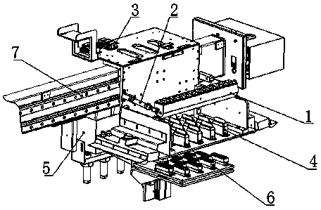
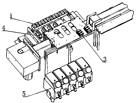
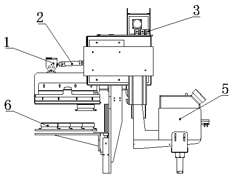
[0031] Embodiment 1: The constant liquid level hydraulic ink supply system of this embodiment includes a mounting base, and a printing nozzle is arranged on the mounting base, and the printing nozzle is equipped with an ink sac device, and the ink sac device includes a plurality of ink The capsule cavity, the upper end of the ink capsule cavity is equipped with an ink capsule cavity gland, and the ink capsule cavity is equipped with an ink capsule ink inlet, an ink capsule ink outlet and a An ink bag heating tube for heating the ink, and an ink bag soft film is arranged between the ink bag cavity and the ink bag cavity gland.
Embodiment 2
[0032] Embodiment 2: The constant liquid level hydraulic ink supply system of this embodiment includes a mounting base, and a printing nozzle is arranged on the mounting base, and the printing nozzle is equipped with an ink sac device, and the ink sac device includes a plurality of ink The capsule cavity, the upper end of the ink capsule cavity is equipped with an ink capsule cavity gland, and the ink capsule cavity is equipped with an ink capsule ink inlet, an ink capsule ink outlet and a An ink sac heating tube for heating the ink, and an ink sac soft membrane is arranged between the ink sac cavity and the ink sac cavity gland; the ink sac soft membrane is made of silica gel.
Embodiment 3
[0033] Embodiment 3: The constant liquid level hydraulic ink supply system of this embodiment includes a mounting base, and a printing nozzle is arranged on the mounting base, and the printing nozzle is equipped with an ink sac device, and the ink sac device includes a plurality of ink The capsule cavity, the upper end of the ink capsule cavity is equipped with an ink capsule cavity gland, and the ink capsule cavity is equipped with an ink capsule ink inlet, an ink capsule ink outlet and a The ink bag heating tube for heating the ink, the soft film of the ink bag is arranged between the cavity of the ink bag and the cover of the cavity of the ink bag; the soft film of the ink bag is made of silica gel; the soft film of the ink bag The thickness of the ink bag is 0.4-0.6mm, and the hardness of the soft membrane of the ink bag is 29-31 Shore hardness.
PUM
 Abstract
Description
Claims
Application Information
 - R&D
- Intellectual Property
- Life Sciences
- Materials
- Tech Scout
- Unparalleled Data Quality
- Higher Quality Content
- 60% Fewer Hallucinations
Browse by: Latest US Patents, China's latest patents, Technical Efficacy Thesaurus, Application Domain, Technology Topic, Popular Technical Reports.
© 2025 PatSnap. All rights reserved.Legal|Privacy policy|Modern Slavery Act Transparency Statement|Sitemap|About US| Contact US: help@patsnap.com


