
Ink gun for printer and its manufacturing method

A manufacturing method and printing device technology, applied in printing and other fields, can solve the problems of affecting the ink supply of the inkjet head, the inkjet work is not smooth, the flow rate cannot be quite stable, etc., and achieve the effect of smooth ink supply

Inactive Publication Date: 2003-06-11
WEISHUO SCI & TECH
View PDF6 Cites 0 Cited by
  • Summary
  • Abstract
  • Description
  • Claims
  • Application Information

AI Technical Summary

Problems solved by technology

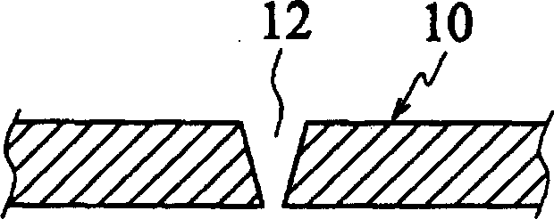
[0006] In this way, when the ink in the ink cartridge flows into the heating element through the ink channel 12, which is wide at the top and narrow at the bottom, its flow rate cannot be quite stable, so that the ink supply of the inkjet head is affected, so that the inkjet operation is not smooth.

Method used


Image

  • Ink gun for printer and its manufacturing method
  • Ink gun for printer and its manufacturing method
  • Ink gun for printer and its manufacturing method

Examples


Embodiment Construction

[0019] Detailed description of the preferred embodiment

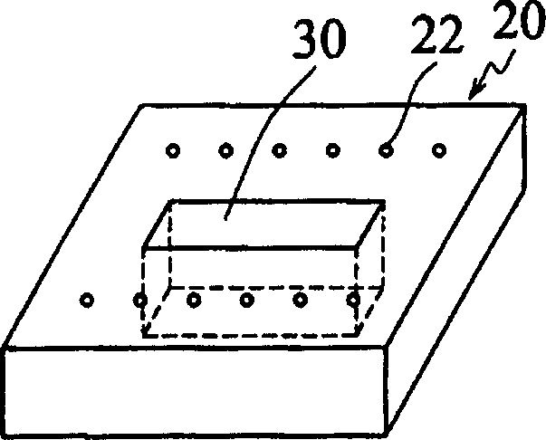
[0020] see figure 2 , the present invention is used for the inkjet head of printing device and its manufacturing method, and this inkjet head comprises a substrate 20 of silicon dioxide, is provided with a plurality of inkjet elements above the substrate 20, and this embodiment is heating element 22; A nozzle layer (not shown in the figure) is arranged on the top of the substrate 20, and a spray hole (not shown in the figure) is formed on it relative to each heating element 22 of the substrate 20. This is the structure of a general inkjet head, and is not shown here. A detailed description. An ink channel 30 is formed in the center of the substrate 20, through which the ink flows to the heating element 22, so that the inkjet head performs ink jetting.

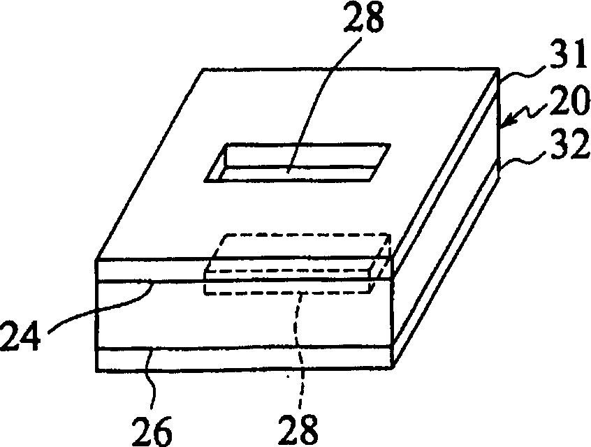
[0021] see image 3 , the present invention is used for the inkjet head of printing device and manufacturing method thereof, at first provides a substrate 20 that is...


PUM


Abstract

A method for making ink jet head of printing device includes the following steps: preparing a base plate with upper surface and undersurface, forming several heating elements and nozzle orifices, respectively applying protection layer on the upper surface and undersurface of said base plate, the above-mentioned protection layers are mutually aligned to form mutually-aligned preset ink channel area, drilling on the above-mentioned preset ink channel area to form the ink channel vertically-passing through the base plate. Sand ink channel possesses identical-size opening on the upper surface and undersurface of said base plte so as to make ink rate more stable and make the ink jet head spray ink more smoothly.

Description

technical field [0001] The invention relates to a manufacturing method of an inkjet head used in a printing device, in particular to a method for forming an ink channel at the central part of the inkjet head so that the ink flows into the inkjet head from the central part of the inkjet head to improve inkjet performance. Inkjet head with stable ink supply to the head and method for manufacturing the same. Background technique [0002] In today's technical field, inkjet heads can be divided into thermal bubble inkjet heads and piezoelectric inkjet heads. Thermal bubble inkjet heads use heating devices to generate high temperatures, and instantly heat the ink on the heating device to generate bubbles. , the ink is ejected onto the print media by the pressure of the air bubbles. The piezoelectric (Piezo) inkjet head uses piezoelectric material as the driving method, that is, the change of the electrode is used to apply pressure to the ink through the film, so that the ink at t...

Claims


Application Information

Patent Timeline
IPC IPC(8): B41J2/14B41J2/16
Inventor 林振华康宏州吴志成
Owner WEISHUO SCI & TECH
Learn More