
Structure of ink gun and ink jet printing system

An inkjet head and ink technology, applied in printing and other directions, can solve the problems of high laser perforation cost, increase the cost of heating chips, and increase the chance of breaking, and achieve the effect of improving product quality rate, production quality rate, and work performance.

Inactive Publication Date: 2007-08-08
MICROJET TECH
View PDF4 Cites 0 Cited by
  • Summary
  • Abstract
  • Description
  • Claims
  • Application Information

AI Technical Summary

Problems solved by technology

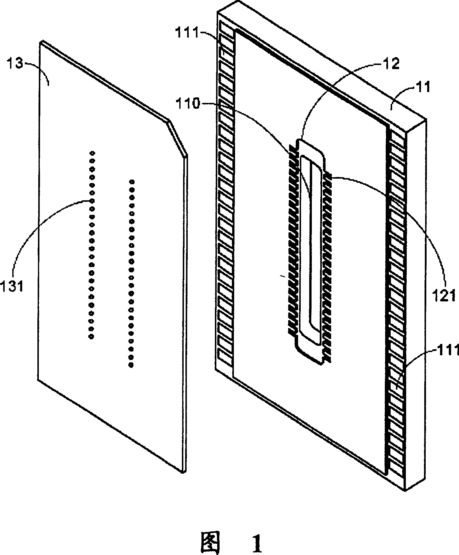
[0007] (1) The step of forming the central ink supply port 110 of the heating chip 11 is usually performed by a sandblasting process or a laser perforation process, wherein the cleanliness of the sandblasting process is relatively poor, while the laser perforation is costly and has material limitations
[0008] (2) The process of forming the central ink supply port 110 of the heating chip 11 is likely to cause cracks in the heating chip 11, so that the heating chip 11 may be broken or the circuit may be damaged in subsequent processes or normal use, so that the inkjet head cannot operate normally
[0009] (3) The heating chip 11 with the central ink supply port 110 has a weakened structural strength, so the chance of fracture increases, resulting in a lower yield
[0010] (4) The two rows of heating resistors on the heating chip 11 around the two sides of the central ink supply port 110 share one ink supply port, so it is easy to have ink supply problems and cross-talk. The phenomenon that each inkjet cavity interacts with each other, which adversely affects the performance of the inkjet head
[0011] (5) For the sake of making the central ink supply port 110, the heating chip 11 inevitably needs to have a considerable size, which greatly increases the cost of manufacturing the heating chip

Method used


Image

  • Structure of ink gun and ink jet printing system
  • Structure of ink gun and ink jet printing system
  • Structure of ink gun and ink jet printing system

Examples


Embodiment Construction

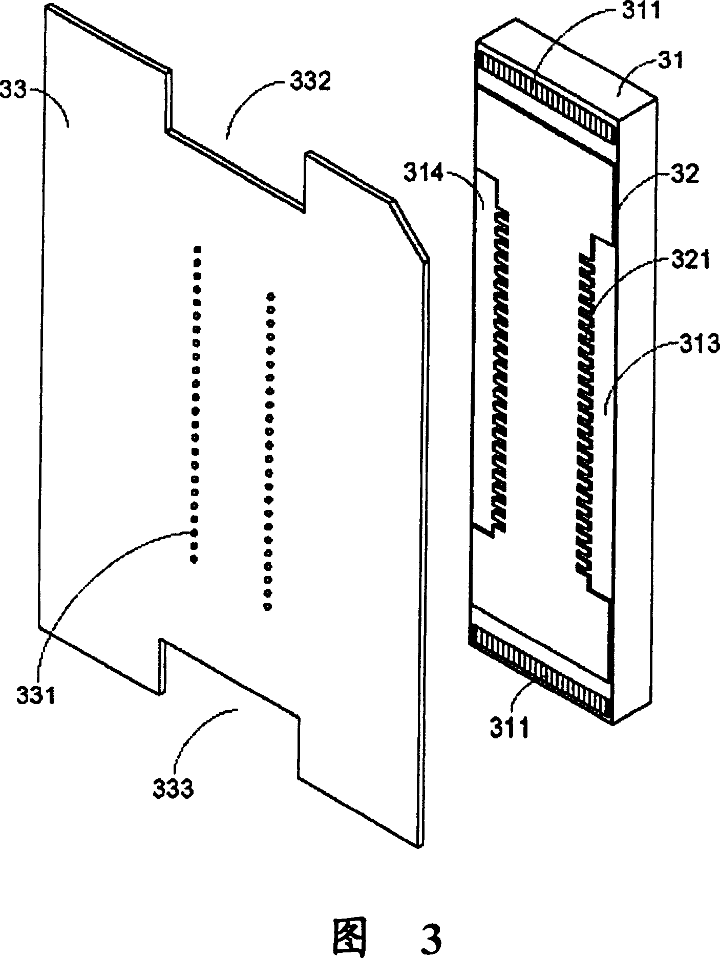
[0041] Please see Fig. 3, the structure of the inkjet head according to the first preferred embodiment of the present invention is mainly composed of a heater IC (heater IC) 31, a barrier layer (barrier layer) 32 and a nozzle plate (nozzle plate) 33 . The heating chip 31 is substantially rectangular, with welding pads 311 on its upper and lower edges. The barrier layer 32 is formed on the heating chip 31 , and together with the heating chip 31 forms an ink supply channel and a plurality of ink cavities 321 . The heating chip 31 is provided with a heating resistor (not shown) corresponding to each ink cavity 321 . The orifice sheet 33 is substantially in the shape of an “H”, and a plurality of orifices 331 corresponding to the ink cavity 321 are disposed above it.

[0042] The feature of the present invention is that when the barrier layer 32 is formed on the heating chip 31, the heating chips 313 and 314 on the left and right sides will be exposed (that is, the barrier layer...


PUM


Abstract

An ink-jet head and its ink-jet print system are disclosed. Said ink-jet head for jetting ink onto a medium has a heating chip, a barrier layer on said heating chip but exposing the left and right ends of said heating chip to form an ink supplying channel and multiple ink cavities, and an orifice sheet with multiple spray orifices relative to said ink cavities and cooperating with said exposed left and right end of heating chip to form the first and the second ink supplying openings. The ink is sprayed from ink box onto medium via said ink supplying openings, ink supplying channel and multiple ink cavities.

Description

(1) Technical field [0001] The invention relates to an inkjet head structure of an ink cartridge, in particular to an inkjet head structure with reduced heating chip size. The present invention also relates to an inkjet printing system using the inkjet head structure. (2) Background technology [0002] With the gradual development of personal computers, ink jet printers have become very common interface devices, widely used in homes, personal studios, and even in various industries. The main advantages of inkjet printers are low price, low noise during operation, and excellent printing quality, and they can be printed on various media, such as general paper, special inkjet printing paper, photo paper, and special transparencies. [0003] The mechanism that controls the release of ink droplets from the printhead to the inkjet media is one of the important factors to be considered in the design of the ink cartridge. Generally speaking, there are mainly two ways of ejecting i...

Claims


Application Information

Patent Timeline
Patent Type & Authority Patents(China)
IPC IPC(8): B41J2/14
Inventor 林富山张英伦余荣候
Owner MICROJET TECH
Learn More