Developer accommodating unit, process cartridge and image forming apparatus

a technology for developing equipment and process cartridges, which is applied in electrographic process equipment, instruments, optics, etc., can solve the problems of becoming further difficult to peel off the sealing member and the difficult toner seal material, and achieve the effect of stably providing a developer

Active Publication Date: 2016-03-22
CANON KK
View PDF66 Cites 41 Cited by
  • Summary
  • Abstract
  • Description
  • Claims
  • Application Information

AI Technical Summary

Benefits of technology

[0011]A principal object of the present invention is to provide a developer accommodating unit, a process cartridge and an image forming apparatus which are capable of peeling off a sealing member with reliability even in the case where peeling strength for peeling off a bonding portion between the sealing member and an accommodating portion thereby to stably supply a developer.

Problems solved by technology

However, in the case where peeling strength for peeling off a bonding portion between the toner seal material and the accommodating portion 138 is large or in the case of a large-sized process cartridge, the developer stirring member is deformed and thus it becomes difficult to peel off the toner seal material to unseal the opening in some cases.
Further, in the case where a flexible container is used as a developer accommodating portion, also a factor of deformation of the flexible container is added, so that it becomes further difficult to peel off the sealing member such as the toner seal material to unseal the opening in some cases.

Method used


Image

  • Developer accommodating unit, process cartridge and image forming apparatus
  • Developer accommodating unit, process cartridge and image forming apparatus
  • Developer accommodating unit, process cartridge and image forming apparatus

Examples


first embodiment

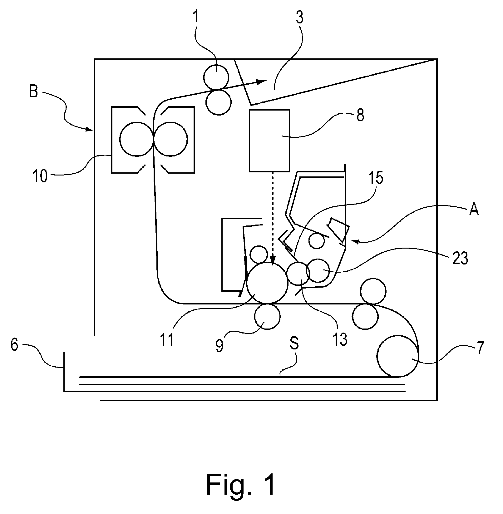
[0038]FIG. 1 is a sectional view of an image forming apparatus in this embodiment of the present invention.

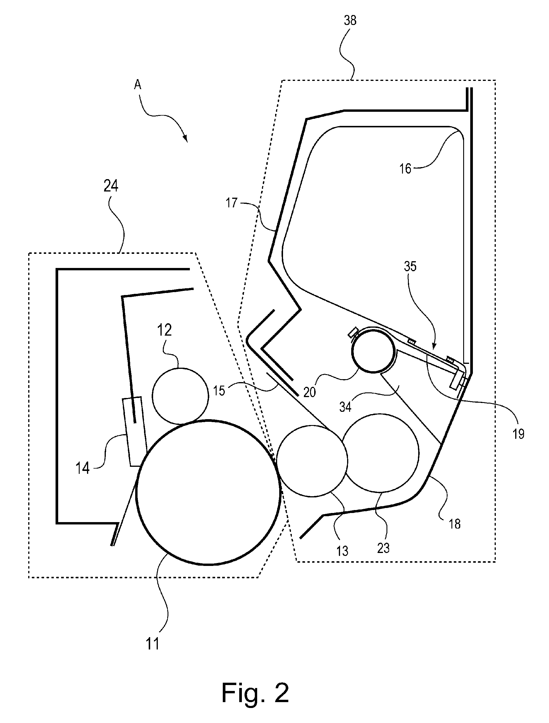
[0039]As shown in FIG. 1, the image forming apparatus includes an image forming apparatus main assembly B and a process cartridge A detachably mountable to the image forming apparatus main assembly B. The process cartridge A is mounted in the image forming apparatus main assembly B during image formation.

[0040]Incidentally, the process cartridge A executes, when being mounted in the image forming apparatus main assembly B, at least a part of an image forming process.

[0041]In the image formation, a sheet S (recording material (medium)) is fed by a feeding roller 7 from a sheet cassette 6 mounted at a lower portion of the image forming main assembly B and in synchronism with this sheet feeding, a photosensitive drum 11 (image bearing member) is selectively exposed to light by an exposure device 8 to form a latent image. The developer is supplied to the developing roller 13 by the...

second embodiment

[0114]Second Embodiment of the present invention will be described.

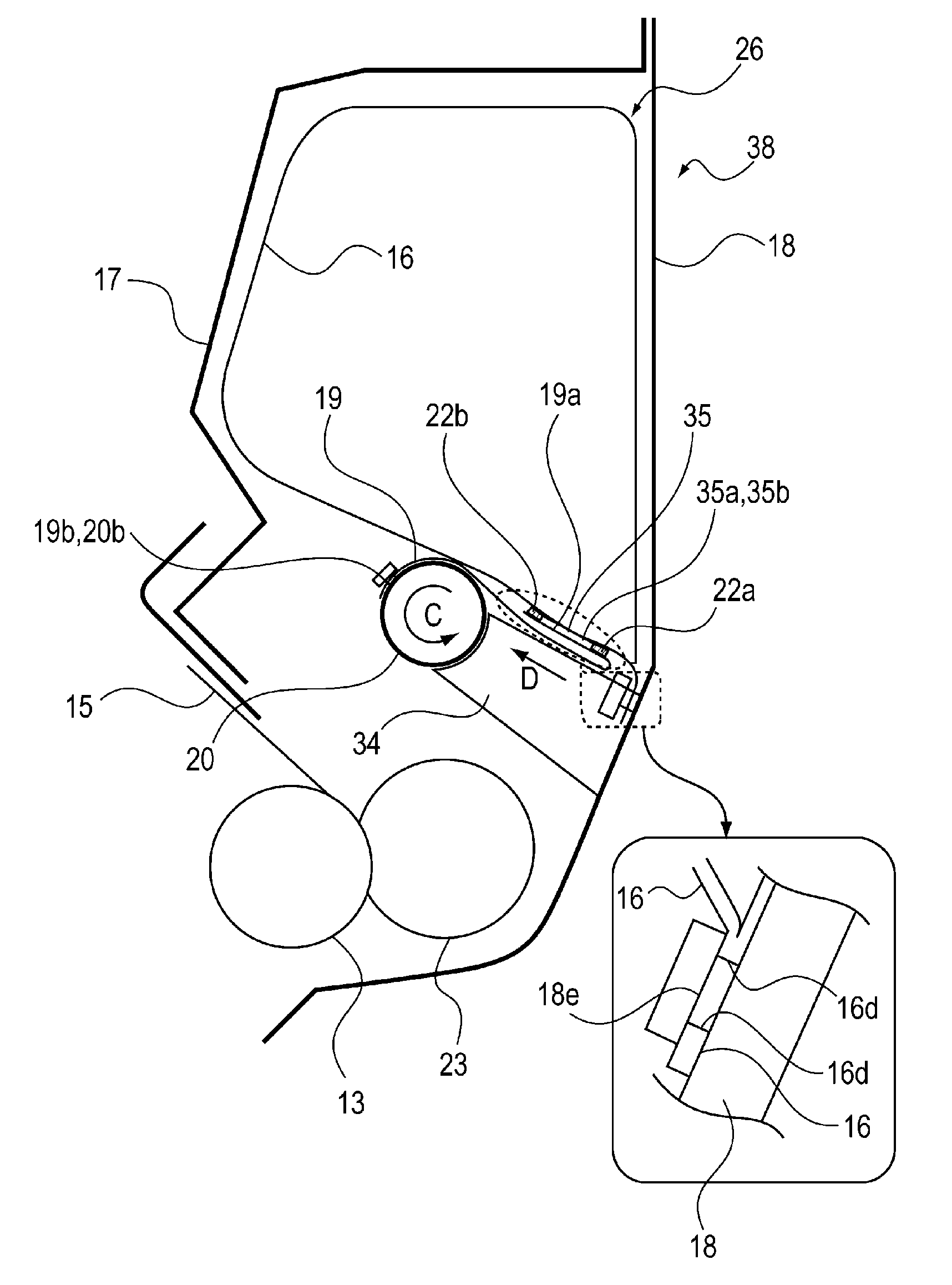
[0115]Parts (a), (b) and (c) of FIG. 16 are sectional views showing a peripheral portion of an opening of a developer bag in Second Embodiment, in which (a) of FIG. 16 shows a state before unsealing, (b) of FIG. 16 shows a state during the unsealing, and (c) of FIG. 16 shows a state after the unsealing. Incidentally, identical or similar constituent elements to those in First Embodiment are represented by the same reference numerals or symbols and will be omitted from redundant description.

[0116]In this embodiment, a limiting portion 34a and a limited portion 20d of the unsealing member 20 are constituted so as to be spaced from each other after unsealing of the sealing member 19. The developer bag 16 and the sealing member 19 have the same constitution as those in First Embodiment, but a positional relationship between the limited portion 20d of the unsealing member 20 and the limiting portion 34d of the container i...

third embodiment

[0121]Third Embodiment of the present invention will be described.

[0122]In this embodiment, a sealing member is provided with a slit through which a limiting portion can enter.

[0123]Parts (a) and (b) of FIG. 17 are schematic views showing a peripheral portion of openings 35a of a developer accommodating container 26 before unsealing in Third Embodiment, in which (a) of FIG. 17 is sectional view with respect to a direction perpendicular to a rotation shaft of an unsealing member 20 and (b) of FIG. 17 shows a cross section including the rotation shaft of the unsealing member 20. Incidentally, identical or similar constituent elements (portions) to those in First Embodiment are represented by the same reference numerals or symbols and will be omitted from redundant description.

[0124]As shown in (a) of FIG. 17, a sealing member 119 is provided with a slit 19e through which a limiting portion 34 can enter. The limiting portion enters through the slit 19e and rotatably limits the unsealin...


PUM


Abstract

A developer accommodating container includes: a flexible container provided with an opening for permitting discharge of a developer; a sealing member, mounted to the flexible container in a state in which the sealing member seals the opening, capable of exposing the opening by being wound up; an unsealing member for winding up the sealing member by being rotated to expose the opening; a frame for accommodating the unsealing member; and a limiting portion for limiting deformation of the unsealing member with respect to a direction of a force applied from the sealing member to the unsealing member when the unsealing member winds up the sealing member.

Description

FIELD OF THE INVENTION AND RELATED ART[0001]The present invention relates to an image forming apparatus, and a developer accommodating unit and a process cartridge which are used in the image forming apparatus.[0002]The image forming apparatus forms an image on a recording material (medium) by using, e.g., an electrophotographic image forming process and may include, e.g., an electrophotographic copying machine, an electrophotographic printer (such as an LED printer or a laser beam printer), an electrophotographic facsimile machine, and the like.[0003]The cartridge refers to a cartridge, prepared by integrally assembling a developing means and a developing device accommodating a developer into a unit, detachably mountable to an image forming apparatus main assembly, or refers to a cartridge, prepared by integrally assembling the developing device and a photosensitive (member) unit including a photosensitive member into a unit, detachably mountable to the image forming apparatus main...

Claims


Application Information

Patent Timeline
Patent Type & Authority Patents(United States)
IPC IPC(8): G03G15/08G03G21/16
CPCG03G15/0882G03G15/0841G03G15/0898G03G21/1676G03G2215/0682G03G2215/0687G03G2215/0875
Inventor MATSUZAKI, HIROOMIYASUI, KOJIROYAMAGUCHI, KOJIMATSUSHITA, MASAAKI
Owner CANON KK
Why Eureka
Try Eureka