Tank and printer including tank

a printer and tank technology, applied in the direction of printing, thin material processing, transportation and packaging, etc., can solve the problems of ink splattering on the floor, the inability to stably supply ink to the liquid discharge recording portion, and the difficulty in maintaining the seal properties of the connection portion between the main tank and the main tank. to achieve the effect of stably supply

Active Publication Date: 2015-02-24
CANON KK
View PDF50 Cites 44 Cited by
  • Summary
  • Abstract
  • Description
  • Claims
  • Application Information

AI Technical Summary

Benefits of technology

[0015]According to the present invention, deviation of the valve for closing the liquid supply port of a tank can be prevented, bubble releasability during atmosphere introduction of the bubbles that are produced when supplying the liquid from the tank can be improved, and the liquid can be stably supplied to a liquid discharge head.
[0016]Further features of the present invention will become apparent from the following description of exemplary embodiments with reference to the attached drawings.

Problems solved by technology

There is consequently the problem that it is difficult to maintain the seal properties of the connection portion between the main tank 401 and the ink tank unit 402.
In addition, if the ink tank itself is accidentally dropped, the position of the sealing valve deviates as described above, so that the problem of ink splattering onto a user or the floor can occur.
Therefore, bubble releasability from the connection portion 503 deteriorates when ink supply (arrow P) is performed simultaneously with air introduction (arrow Q), so that there is a risk that the ink cannot be stably supplied to a liquid discharge recording portion.

Method used


Image

  • Tank and printer including tank
  • Tank and printer including tank
  • Tank and printer including tank

Examples


first embodiment

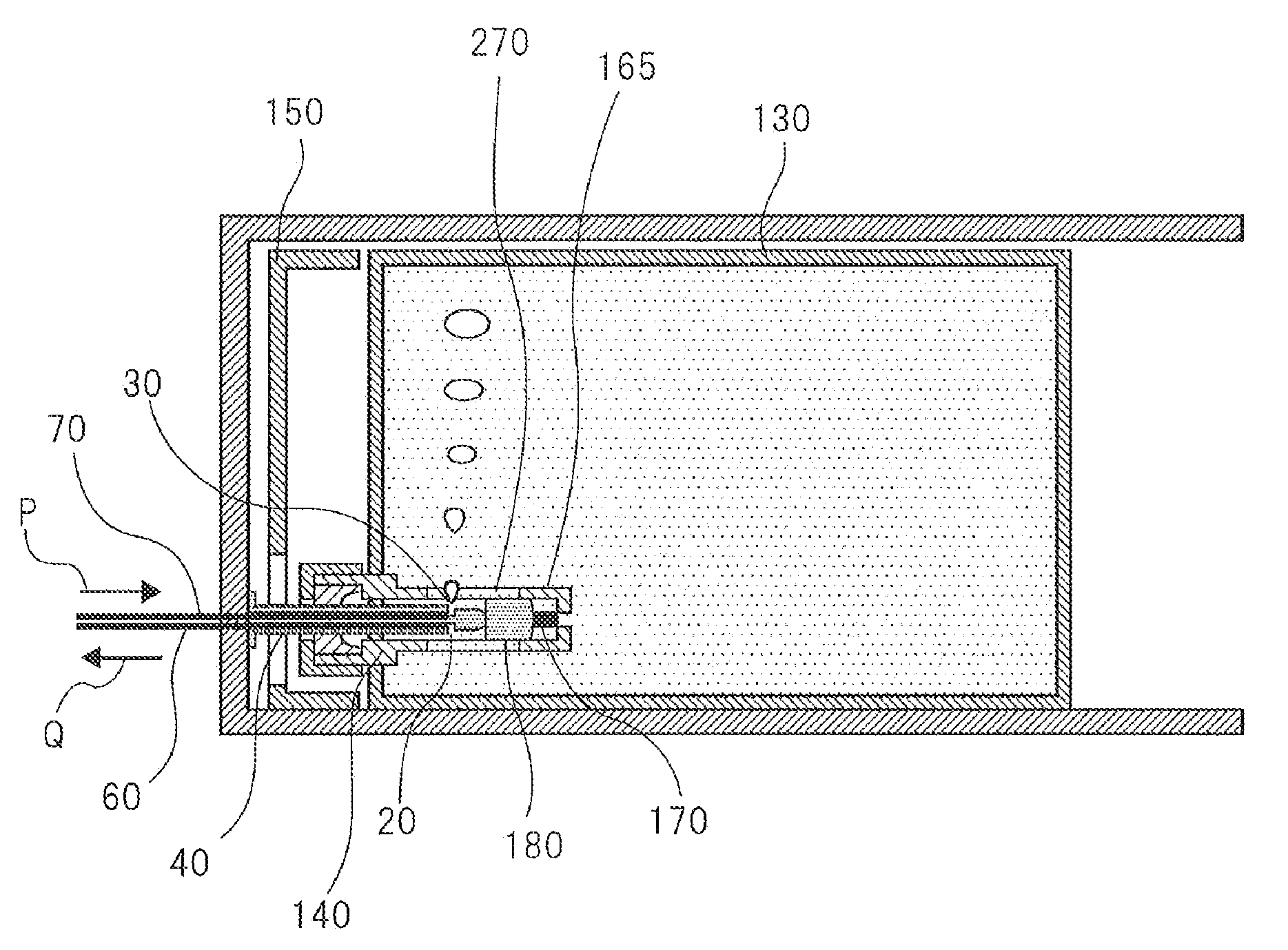
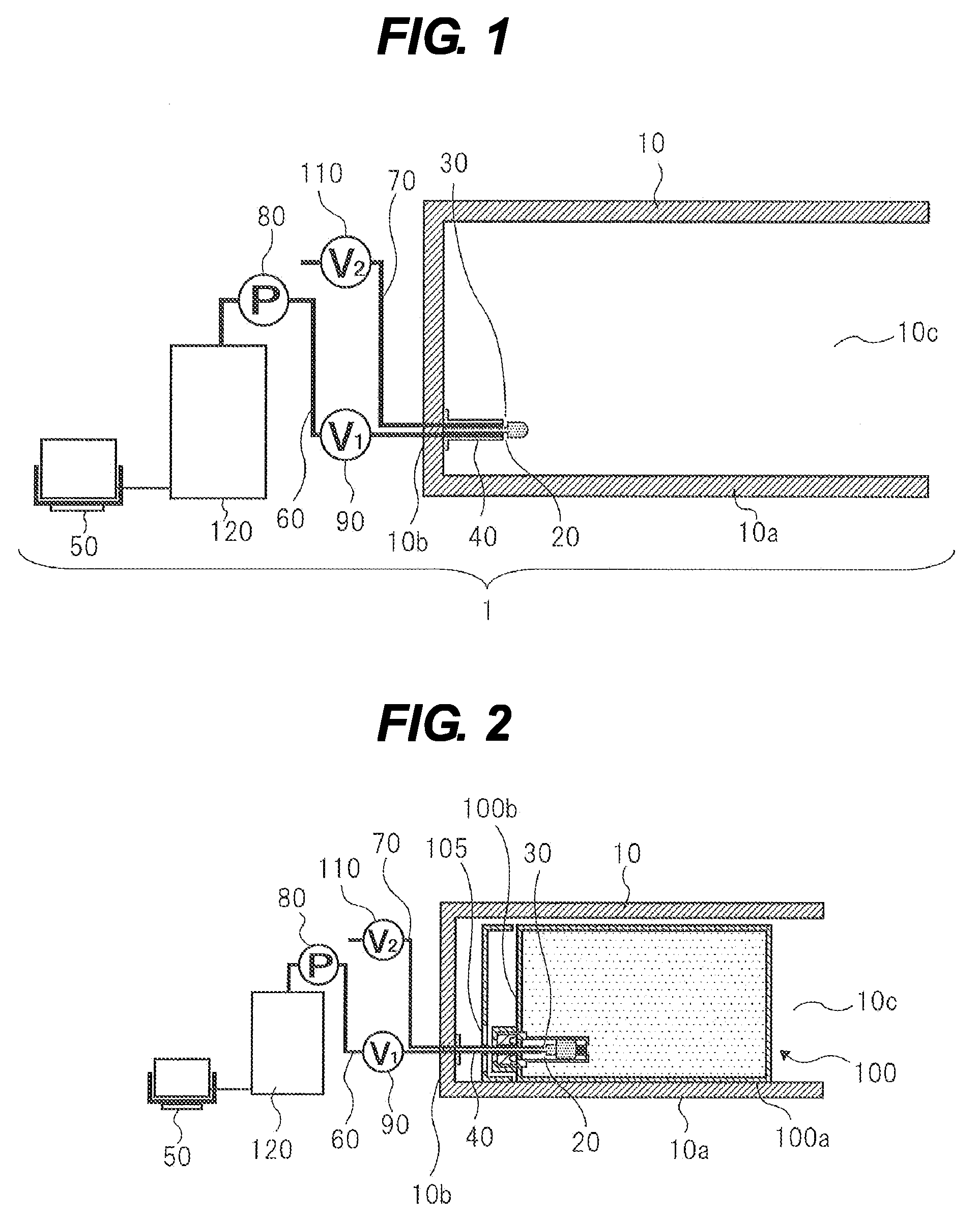
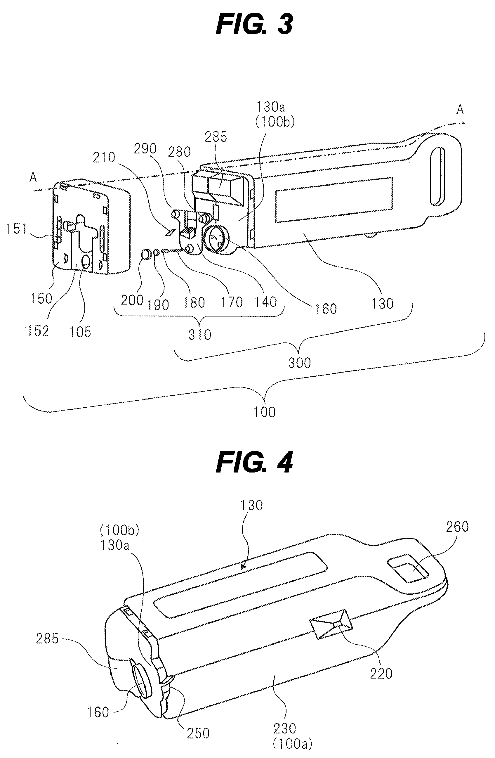
[0034]A first embodiment according to the present invention will now be described with reference to the drawings. The first embodiment will be described using as examples an ink jet printer that performs recording by discharging ink toward a recording medium and the ink tank that is used for this printer. However, these are merely examples. The shape, configuration, and materials of these examples may be changed in any way, so long as such a change does not depart from the concept of the present invention. Further, except for FIGS. 3 and 4, the drawings illustrate an ink tank. However, this was done for convenience so that the ink tank configuration according to the embodiment of the present invention could be illustrated in a simplified or schematic manner.

Printer Configuration

[0035]The configuration of the ink jet printer (hereinafter, “printer”) according to the present embodiment will now be described with reference to FIGS. 1 and 2.

[0036]A printer 1 illustrated in FIGS. 1 and 2...


PUM


Abstract

The invention is to prevent positional deviation of a sealing valve, improve bubble releasability during atmosphere introduction, and stably supply ink to a recording head. The configuration is provided with an opening 270 on an upper portion of a cylindrical regulating body 165 of a joint base 140 in a state where an ink tank 100 is mounted on a connection unit 10 of a printer.

Description

TECHNICAL FIELD[0001]The present invention relates to a tank for storing ink used for an ink jet printer, and an ink jet printer which performing recording by discharging the stored ink. Further, the present invention relates to a tank used for an ink jet printer that consumes a large amount of ink, and an ink jet printer having such a tank removably mounted thereon.BACKGROUND ART[0002]In ink jet printers that consume large amounts of ink, a stationary type of ink tank is employed. When this type of ink tank is used, the configuration of a connection body for ink supply provided on the ink jet printer side can be broadly classified into two types.[0003]One type uses a needle-shaped body as the connection body. In this type, ink is supplied by sticking the needle-like body into a rubber seal provided in an ink supply port in the ink tank. The other type uses a tube-shaped body as the connection body. In this type, a cylindrical regulating body, which includes a valve and a spring-sha...

Claims


Application Information

Patent Timeline
Patent Type & Authority Patents(United States)
IPC IPC(8): B41J2/175
CPCB41J2/1752B41J2/17513B41J2/17523Y10T137/598
Inventor TAKADA, HITOSHIKOTAKI, YASUOKUBO, KOICHIHAYASHI, HIROKINANJO, TATSUOMIYASHITA, TAKEHO
Owner CANON KK
Why Eureka
Try Eureka