Multi-head embroidery machine

An embroidery machine, multi-head technology, applied in the direction of embroidery machine, embroidery machine mechanism, automatically controlled embroidery machine, etc., can solve problems such as troublesome adjustment of pressing cloth height, influence of processing cloth movement, excessive running speed, etc., to achieve fast automatic Correcting the effect of the height of the presser foot

Active Publication Date: 2008-01-02
BARUDAN KK
View PDF1 Cites 8 Cited by
  • Summary
  • Abstract
  • Description
  • Claims
  • Application Information

AI Technical Summary

Problems solved by technology

However, when adjusting manually, it is troublesome to adjust the height of the press cloth when the processing conditions of the embroidery pattern change, and there is a problem that the adjustment is slow.
In addition, during automatic adjustment, since the timing of adjusting the cloth pressing height programmed in the embroidery data is only based on the cloth thickness, after the running speed of the embroidery machine changes, when the cloth pressing height is too large or insufficient, there will be disorder in the processed cloth. Moving (ばたつく) or remaining indentations on the processed cloth
The inventors of the present invention found that the cloth pressing height adjusted according to the cloth thickness is suitable for low operating speed, but it is insufficient when the operating speed is high, which affects the movement of the processed cloth or leaves indentations on the processed cloth.
On the contrary, the cloth pressing height corresponding to the cloth thickness adjustment is suitable for the high running speed, but it is too large when the running speed is low, and there is a phenomenon that the processed cloth flutters

Method used


Image

  • Multi-head embroidery machine
  • Multi-head embroidery machine
  • Multi-head embroidery machine

Examples


Embodiment

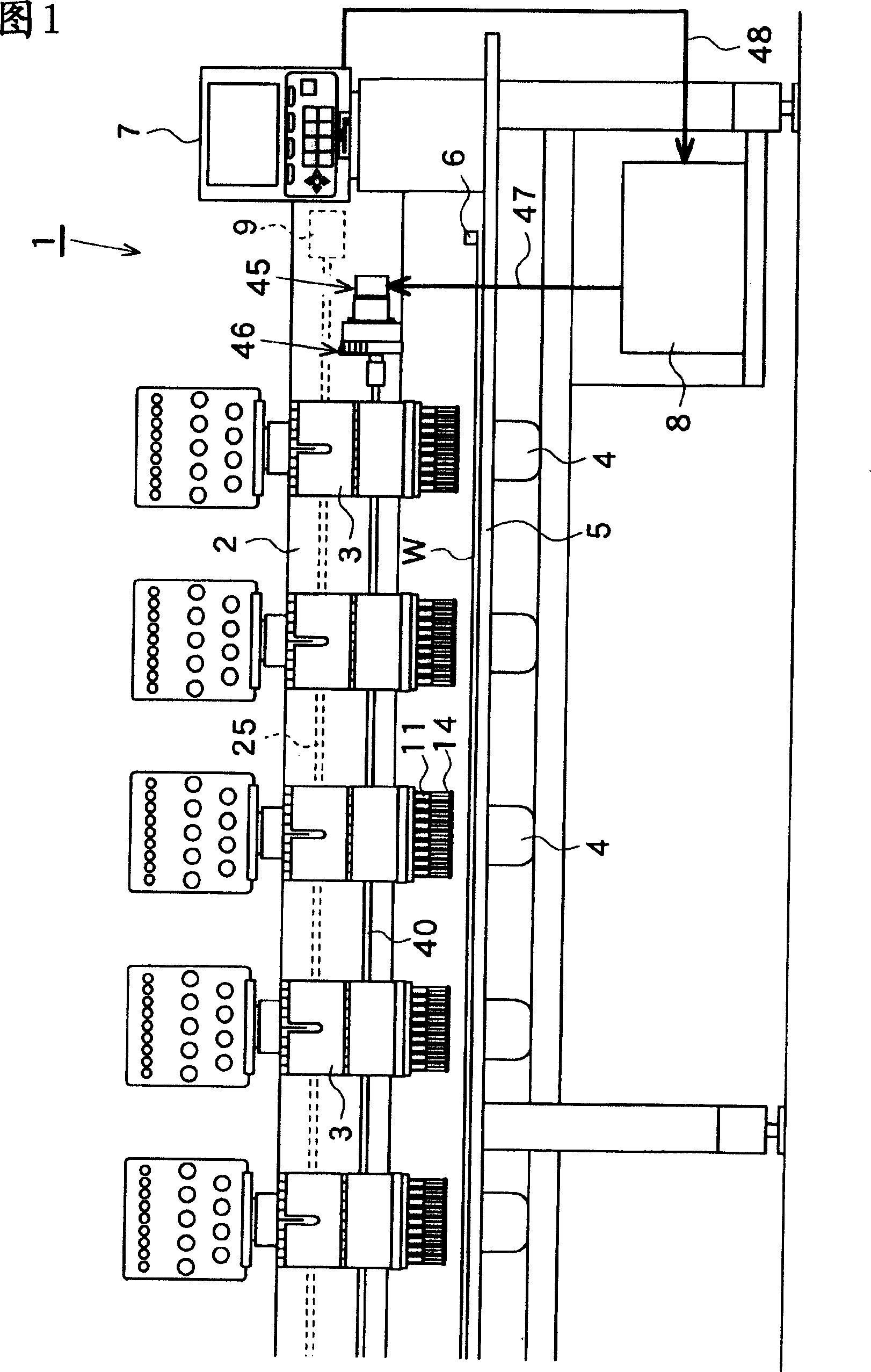
[0025] Next, the structure of each part of the multi-head embroidery machine 1 will be described in detail based on the embodiment. As shown in FIG. 1 , a plurality of heads 3 are arranged side by side on a frame 2 of a multi-head embroidery machine 1 , a base 4 is provided on the underside of each head 3 , and a table 5 is provided at the same height as the base 4 . Place the sewing frame 6 on the table 5 for conveying the processed cloth W forward, backward, left, and right, an operation panel 7 with the function of editing embroidery pattern data is set at the right end of the table 5, and all electric appliances for controlling the embroidery machine 1 are set on the lower side of the table 5 Control panel 8 of the device.

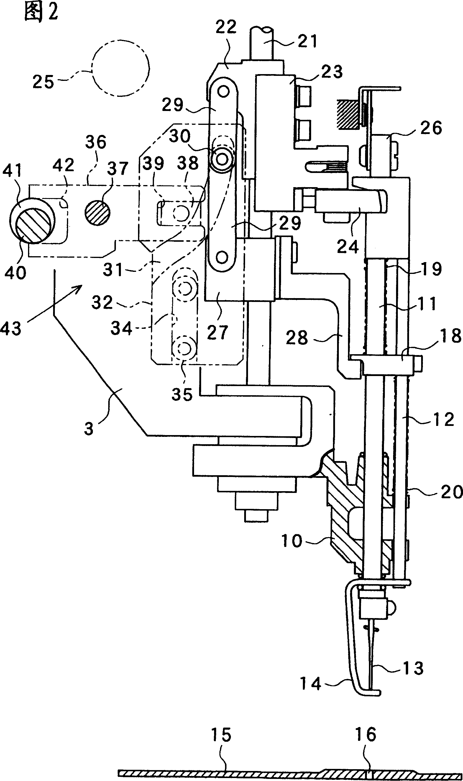
[0026] As shown in FIG. 2, a rotating body 10 is provided at the lower part of the machine head 3, and is rotated in a horizontal plane by a color changing mechanism not shown in the figure. A plurality of needle bars 11 and cloth pressing bars 12 are...


PUM


Abstract

The multi-head embroidery machine of the invention can self-correct the height of the pressing cloth rapidly according to the running speed of the embroidery machine to realize the optimization. A plurality of machine heads (3) of the multi-head embroidery machine (1) are arranged with a regulating mechanism which adjusts the height of the cloth pressing foot (14) at the bottom dead center position. The machine uses the connecting shaft (40) to connect each regulating mechanism and uses the actuator (45) to drive the connecting shaft (40). The operation board (7) is arranged with a display part (61) which uses picture to represent the needle number information of the embroidery riffled data and an inputting part (60) which is inputted with the cloth depth relative to the needle number information. The control board (8) corrects the height of the cloth pressing foot (14) at the bottom dead center position according to the inputting cloth depth and the spindle speed controlled actuator (45). The actuator (45) is additionally arranged with a display device (46) which displays the current value of the cloth pressing height.

Description

technical field [0001] The present invention relates to a multi-head embroidery machine with the function of adjusting the height of the presser foot (cloth pressing height) at the bottom dead center position. Background technique [0002] Now, it is well known that a plurality of heads (machine heads) are provided with a multi-head embroidery machine that is provided with an adjustment mechanism that adjusts the height of the press cloth corresponding to the thickness of the processed cloth (cloth thickness). For example, such a technology is described in Patent Document 1, that is, cams for adjusting the height of the cloth are provided on each machine head, the cams are connected by a connecting shaft, a handle is provided at one end of the connecting shaft, and the operator rotates the handle by hand. Adjust the cloth pressing height of each head according to the cloth thickness. In addition, it also records an embroidery machine that uses a pulse motor to drive a conne...

Claims


Application Information

Patent Timeline
IPC IPC(8): D05C7/00D05C13/00D05B29/02
Inventor 村田吉广
Owner BARUDAN KK
Why Eureka
Try Eureka