Transformer having drag-head switch and transformation method of transformer drag-head

A transfer switch and transformer technology, applied in the field of transformers, can solve the problems of high transportation costs, achieve the effect of easy installation and suppression of gas leakage

Active Publication Date: 2010-12-29
KK TOSHIBA
View PDF7 Cites 0 Cited by
  • Summary
  • Abstract
  • Description
  • Claims
  • Application Information

AI Technical Summary

Problems solved by technology

In addition, in order to prevent the bearing of the drive rod from being eccentric due to the action of external force during transportation, it is necessary to protect the shaft during transportation, such as fixing, so the transportation cost is high.

Method used


Image

  • Transformer having drag-head switch and transformation method of transformer drag-head
  • Transformer having drag-head switch and transformation method of transformer drag-head
  • Transformer having drag-head switch and transformation method of transformer drag-head

Examples


Embodiment Construction

[0041] Embodiments of a transformer with a tap changer according to the present invention will be described below with reference to the drawings. Among them, common reference numerals are assigned to identical or similar parts, and repeated explanations thereof will be omitted.

[0042] [First Embodiment]

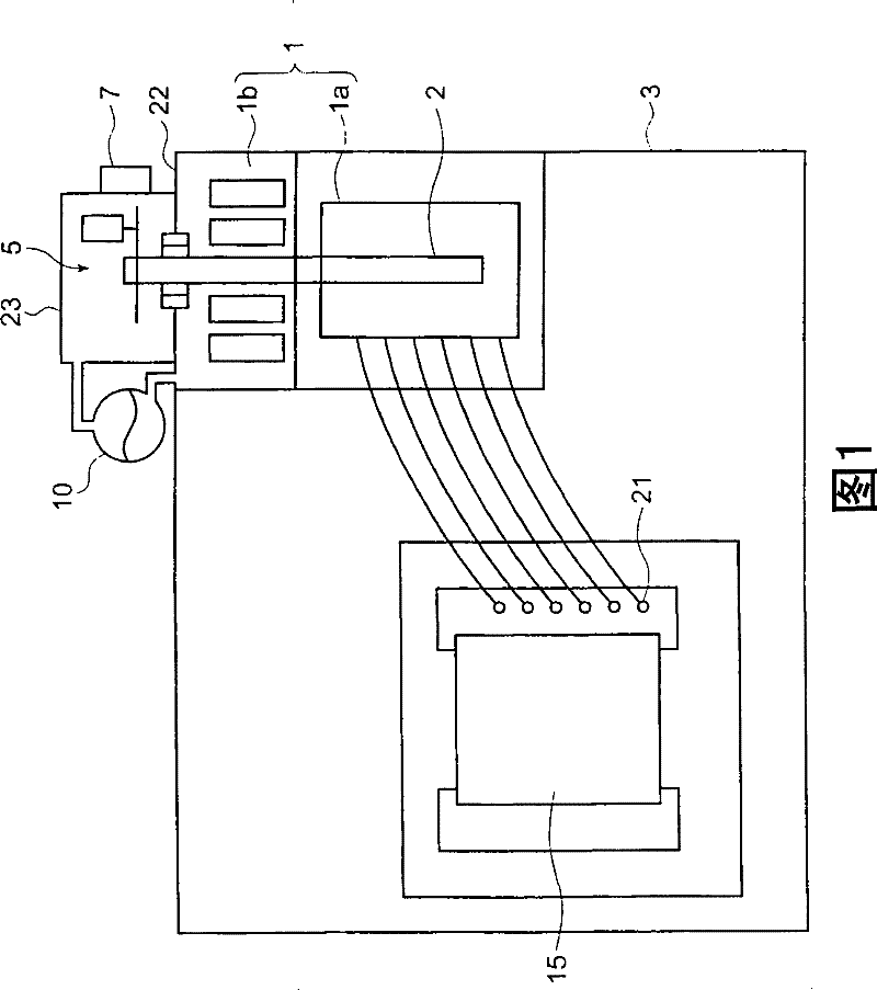
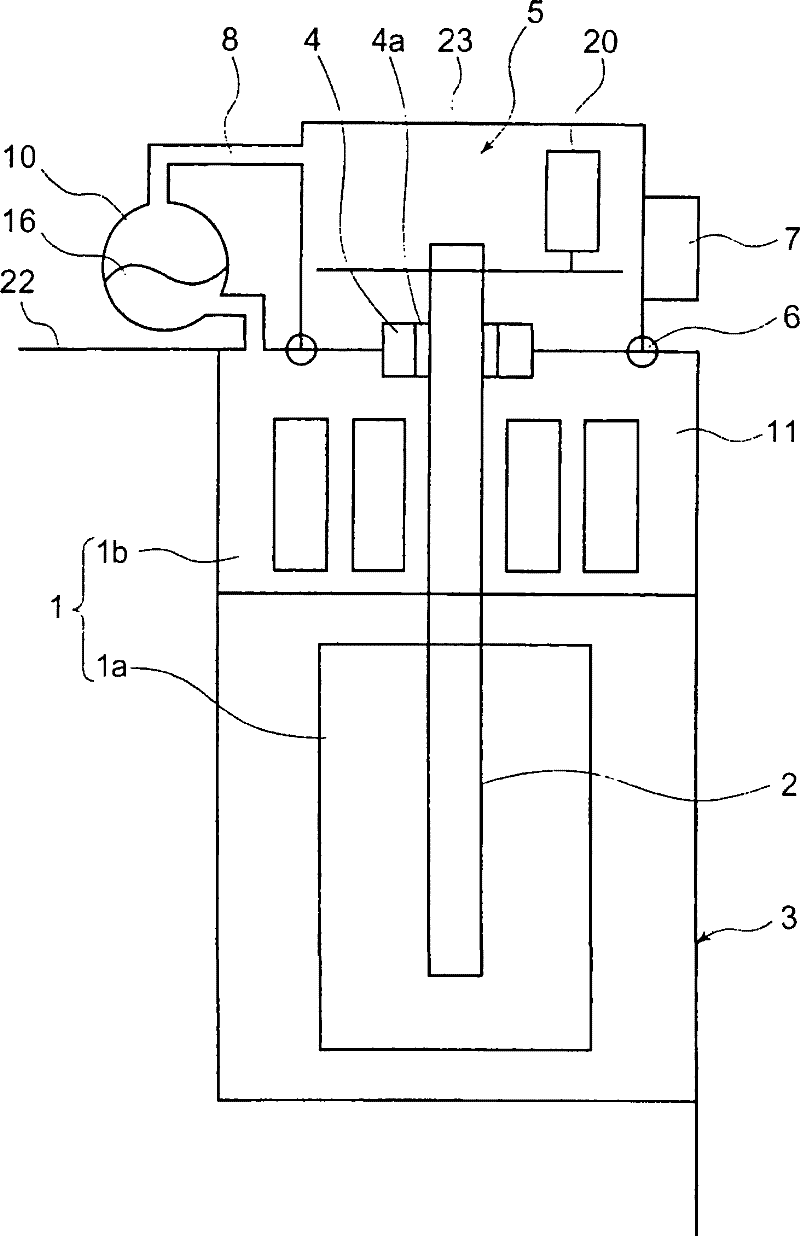
[0043] Referring below to Figure 1 and figure 2 A first embodiment of a transformer with a tap changer according to the present invention will be described. Wherein, Fig. 1 is a longitudinal sectional view of a first embodiment of a transformer with a tap changer of the present invention, figure 2 It is an enlarged longitudinal sectional view of main parts of the transformer with a tap changer in FIG. 1 .

[0044] As shown in the figure, the coil 15 of the transformer is accommodated in the main body casing 3 , and the coil 15 is connected to a plurality of terminals 21 . The tap changer 1 is provided inside the main body housing 3 so as to be in contact with the top pl...


PUM


Abstract

The transformer of the invention comprises: loop (15) with a plurality of terminals (21); insulating medium (11) of the loop (15); tap changing device (1) choosing the connection to the terminals (21); display part (7) displaying the choice positon of the tap changing device (1); driven axis (2) with frame through part (4) formed on main frame (3), which is through the main frame (3) and changes the tap changing device (1). The transformer also comprises: driven unit frame (23) on the main frame (3) and covering the frame through part (4) and driven axis (2); and driven unit (5) in the drivenunit frame (23) and including power source (20) and driving the driven axis (2).

Description

technical field [0001] The invention relates to a transformer with a tap changer and a tap change method of the transformer. Background technique [0002] In the transformer with tap changer in the prior art, the coil converted into electric power by electromagnetic induction is placed in the frame and sealed in an insulating medium. Set a tap in the middle of the coil, and adjust the output voltage or current by changing the connection position of the lead wire. A plurality of taps are provided in one turn of the coil. In a high-voltage transformer, not only the number of taps is large, but also the potential difference between the taps is large. In order to eliminate the heat generated by the flowing current, a liquid insulating medium with a high specific heat is often impregnated. In the case of a gas insulating medium, in order to increase the heat capacity, it is often pressurized and sealed to several atmospheric pressures. [0003] In addition, there are two ways ...

Claims


Application Information

Patent Timeline
Patent Type & Authority Patents(China)
IPC IPC(8): H01F29/04H01H3/32H01F27/14H01H3/28
Inventor 和田治寿泷口幸延
Owner KK TOSHIBA
Why Eureka
Try Eureka