Robot system

A robot system and robot technology, applied in the field of robot systems, can solve the problems of poor operation performance, increased influence of vibration, and increased position of the center of gravity.

Inactive Publication Date: 2016-10-12
SEIKO EPSON CORP
View PDF5 Cites 1 Cited by
  • Summary
  • Abstract
  • Description
  • Claims
  • Application Information

AI Technical Summary

Problems solved by technology

[0005] However, in the robot cell room described in Patent Document 1, when the robot is installed on the ceiling surface, the position of the center of gravity of the robot becomes high, and when the robot vibrates, there is a problem that the influence of the vibration increases.
[0006] In addition, when the robot is installed on the floor, the robot itself becomes an obstacle, and there is a problem that the work performance deteriorates.

Method used


Image

  • Robot system
  • Robot system
  • Robot system

Examples


no. 1 Embodiment approach >

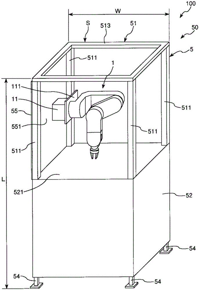
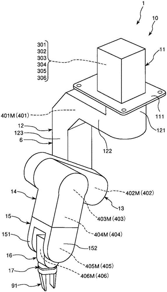
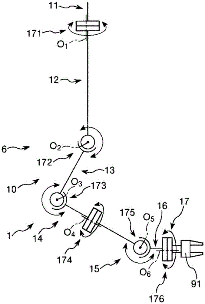
[0052] figure 1 It is a perspective view showing the first embodiment of the robot system of the present invention. figure 2 yes figure 1 A perspective view of the robot of the robotic system shown. image 3 yes figure 1 A schematic diagram of the robot of the robotic system is shown. Figure 4 ~ Figure 6 respectively figure 1 A diagram of the robot in the main view of the robot system shown. Figure 7 ~ Figure 11 respectively for the figure 1 A diagram for explaining the operation of the robot in the robot system shown.

[0053] In addition, in the following, for the convenience of explanation, the figure 1 , Figure 4 ~ Figure 11 The upper side is called "upper" or "upper", and the lower side is called "lower" or "below" (other embodiments) Figure 12 to Figure 14 as well). Additionally, the Figure 1 to Figure 11 The abutment side in the method is called "basal end" or "upstream", and the opposite side (hand side) is called "terminus" or "downstream" (other embo...

no. 2 Embodiment approach >

[0114] Figure 12 It is a perspective view showing the second embodiment of the robot system of the present invention. Figure 13 yes Figure 12 A diagram of the robot in the main view of the robot system shown.

[0115] Hereinafter, the second embodiment will be described, but the description will focus on the differences from the first embodiment described above, and the description of the same matters will be omitted.

[0116] Such as Figure 12 as well as Figure 13 As shown, in the robot system 100 of the second embodiment, a mounting portion 552 on which the base 11 of the robot 1 is mounted is formed above the wall portion 55 of the cell 5 in the vertical direction.

[0117] The shape of the mounting portion 552 is not particularly limited, but in this embodiment, it is formed in a triangular prism shape. Moreover, the orientation of the mounting portion 552 Figure 12 as well as Figure 13 The obliquely downward surface 553 is the first surface inclined with res...

no. 3 Embodiment approach >

[0124] Figure 14 It is a perspective view showing the third embodiment of the robot system of the present invention. Figure 15 yes Figure 14 A diagram of the robot in the main view of the robot system shown.

[0125] Hereinafter, the third embodiment will be described, but the description will focus on the differences from the first embodiment described above, and the description of the same matters will be omitted.

[0126] Such as Figure 14 as well as Figure 15 As shown, in the robot system 100 according to the third embodiment, a mounting portion 554 on which the base 11 of the robot 1 is mounted is formed below the wall portion 55 of the cell 5 in the vertical direction.

[0127] The shape of the mounting portion 554 is not particularly limited, but in this embodiment, it is formed in a triangular prism shape. Moreover, the orientation of the mounting portion 554 Figure 14 as well as Figure 15 The obliquely upper surface 555 is the first surface inclined with...


PUM


Abstract

The invention provides a robot system that can inhibit influence of vibration of robots and improve operation performance of robots in the unit chamber. A robot system includes a cell having a first surface at an angle different from that of a horizontal plane, and a robot provided on the first surface, wherein the robot has an nth (n is an integer number equal to or more than one) arm rotatable about an nth rotation shaft, and an (n+1)th arm provided on the nth arm rotatably about an (n+1)th rotation shaft in a shaft direction different from a shaft direction of the nth rotation shaft.

Description

technical field [0001] The present invention relates to robotic systems. Background technique [0002] Conventionally, a robot including a robot arm is known. In the robot arm, a plurality of arms (arm members) are connected via joints, and the most distal (most downstream) arm is equipped with, for example, a hand as an end effector. The joint part is driven by a motor, and the arm is rotated by driving the joint part. Further, the robot grasps an object with its hands, for example, moves the object to a predetermined place, and performs predetermined operations such as assembly. [0003] In addition, Patent Document 1 discloses a robot unit room including a unit room and a robot installed in the unit room. In the robot cell described in Patent Document 1, the robot is installed on a surface parallel to the horizontal plane, that is, on the ceiling surface of the cell. [0004] Patent Document 1: Japanese Patent Laid-Open No. 2011-21874 [0005] However, in the robot c...

Claims


Application Information

Patent Timeline
Patent Type & Authority Applications(China)
IPC IPC(8): B25J9/00B25J18/00
CPCB25J9/00B25J9/0009B25J18/00B25J9/046B25J21/00
Inventor 赤羽和重吉村和人
Owner SEIKO EPSON CORP
Why Eureka
Try Eureka